Getting Started with the SparkFun Inventor's Kit for Google's Science Journal App
 bri_huang
The Arduino 101
The Arduino 101 is a development board based on the Intel Curie module that leverages the simplicity of the Arduino programming environment. If you got the SIK for Google's Science Journal App, we pre-programmed this board for you to work directly with the Google Science Journal. If you have your own Arduino 101 and need to program it for the Science Journal, you can get the full source-code on github here.

This board has a built-in Bluetooth chip and is pre-programmed to communicate directly with the Science Journal App. This board will allow you to connect a variety of sensors to the Science Journal App through the Analog Pins (A0 - A5) with a little bit of circuit building.
When you've completed your science experiments with the Science Journal and you want to go further, we have a whole series of activities and experiments that you can explore to learn more about programming and electronics using your Arduino 101, but we're getting ahead of ourselves. Let's start with pairing the Arduino 101 to your Science Journal App.
Pairing the Arduino 101 to your Science Journal
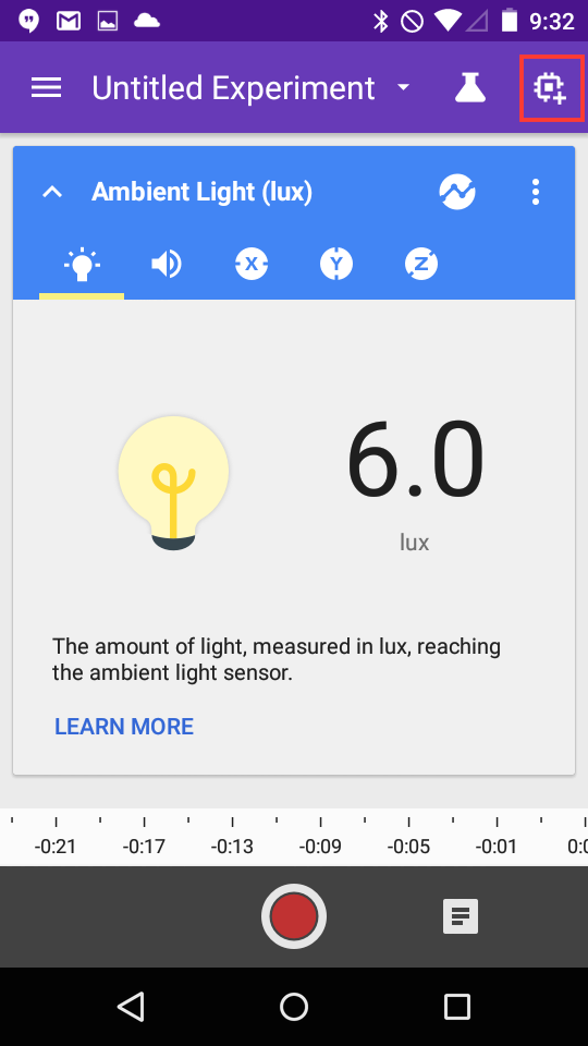
The Arduino 101 will allow you to add external sensors to your Science Journal. First power up the Arduino 101 using either the USB cable, the 9V battery and battery adapter, or the wall adapter. Next, open up the Science Journal App and click on the add device icon in the upper right corner of the screen:
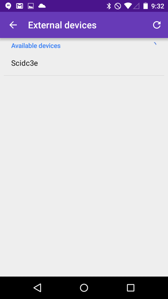
Next, identify the name of the Arduino 101 that you have. It will start with the letters "Sci" for Science and then have 4 extra unique characters that follow it. In our case, it's named Scidc3e.
Configuring the Arduino 101 readings
Tap on this device name to pair it. Now, you have a few options that you can configure for how you want to read sensor data from your Arduino 101. As a default, the Arduino 101 is looking at the voltage on pin A0. The app is configured to show this information as either Rotations or Raw values.
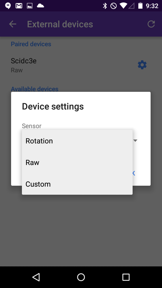
The Rotations setting takes an average of the number of light and dark transitions and estimates the rotations per minute (RPM) that an encoder disk is spinning. We use this in the Wind Spinner project later on. And, the Raw setting will display the voltage as a percentage from 0 to 100. A voltage of 3.3V will show 100%.
Going further with the Custom setting
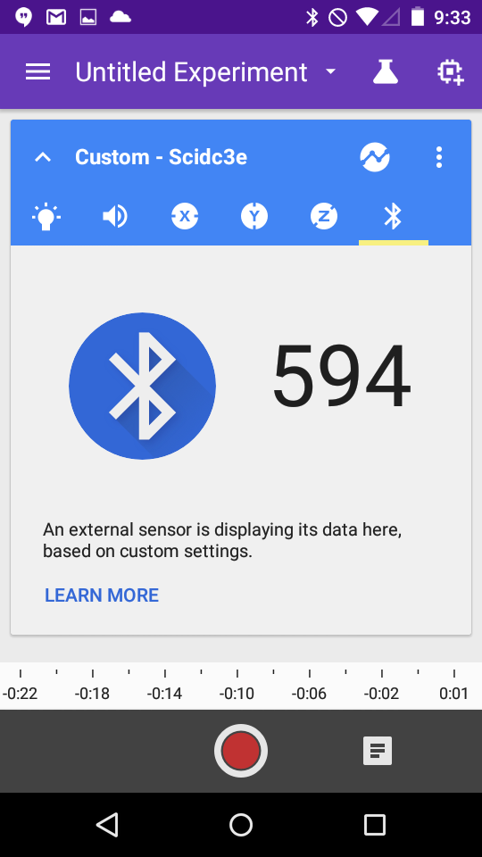
If you want to explore other sensors or see the raw analog-to-digital (ADC) value, you can go into the Custom option. Under this option, you can select any of the available Analog pins on the Arduino 101 (A0 - A5).
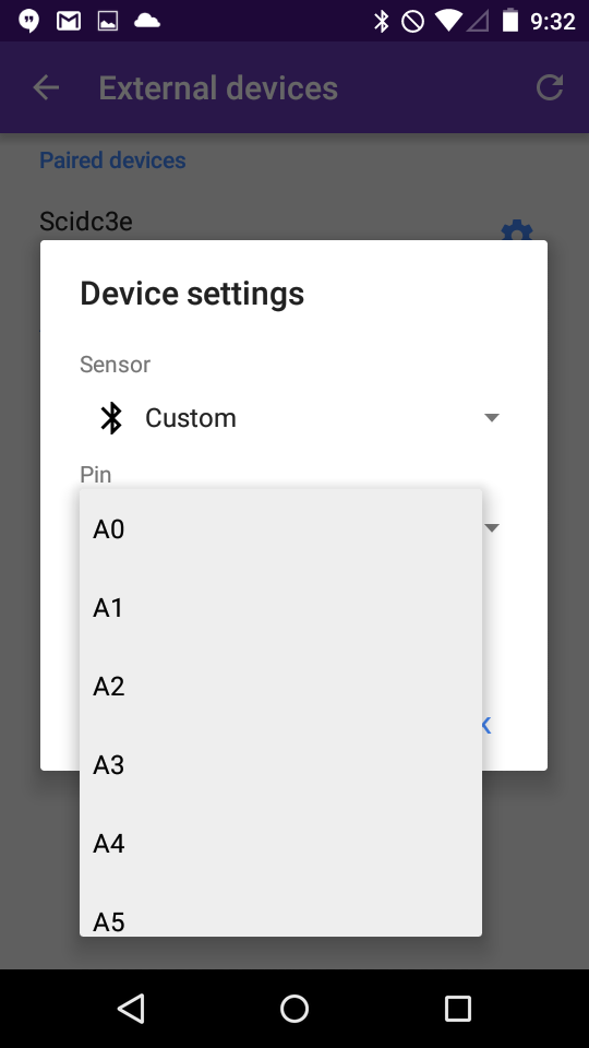
Once you've configured the sensor on the app, tap the back arrow to get back to your experiment, and slide your finger sideways until you see the new icon appear on the right side. For the custom sensor, this will appear as a bluetooth icon, and this will show a value of 0 - 1023 based on the actual sensor reading of the Arduino device. These are really unit-less values, but I'm pretty sure we can still make some good predictions and conclusions based on patterns that we see in the data.
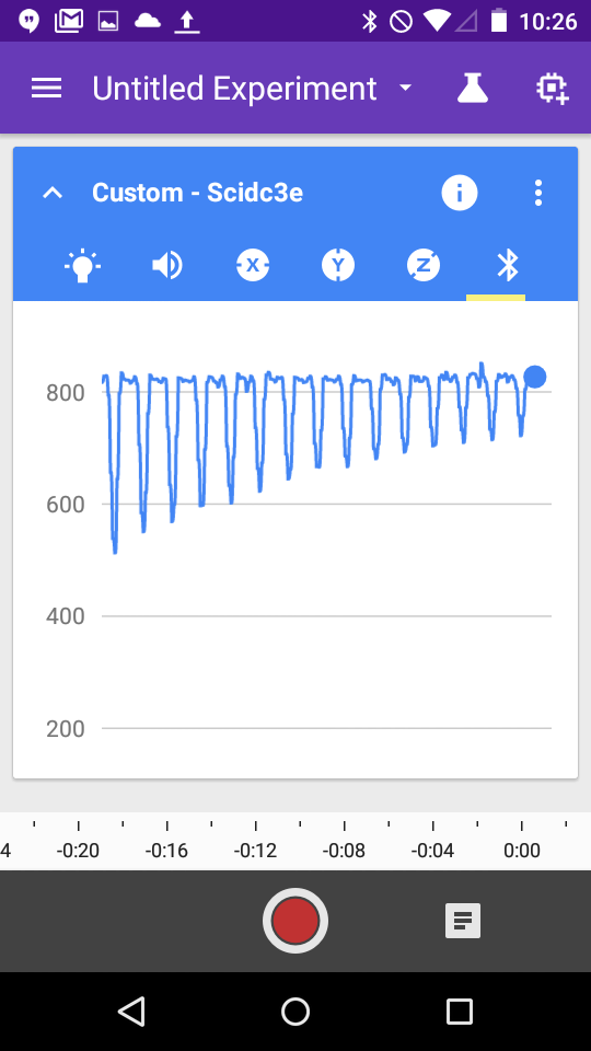
If you've explored all of the features of the app, you know that we can also display this data graphically. Here's a graph of a "pendulum" chandalier that I made swing back and forth over the top of the light sensor.
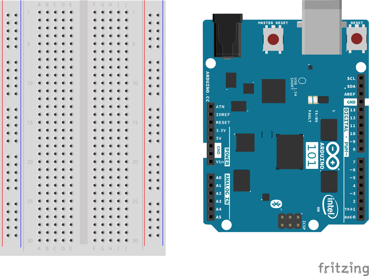
Last thing. If you haven't mounted your Arduino 101 board onto the plastic breadboard holder, you should do that now. Orient the Arduino 101 board and the breadboard (the white thing with a lot of holes in it) so that it looks like the diagram below. There are some little screws that you can use to afix the Arduino 101 board down, and the breadboard has a self-adhesive backing that you can use.
Now you're ready to go and start exploring with the Science Journal and your new Arduino 101 sensor kit. We've included two sensors in the kit that we'll show you how to setup next.