Gator:color ProtoSnap Hookup Guide
Contributors:
 Englandsaurus
Englandsaurus 
Hardware Assembly
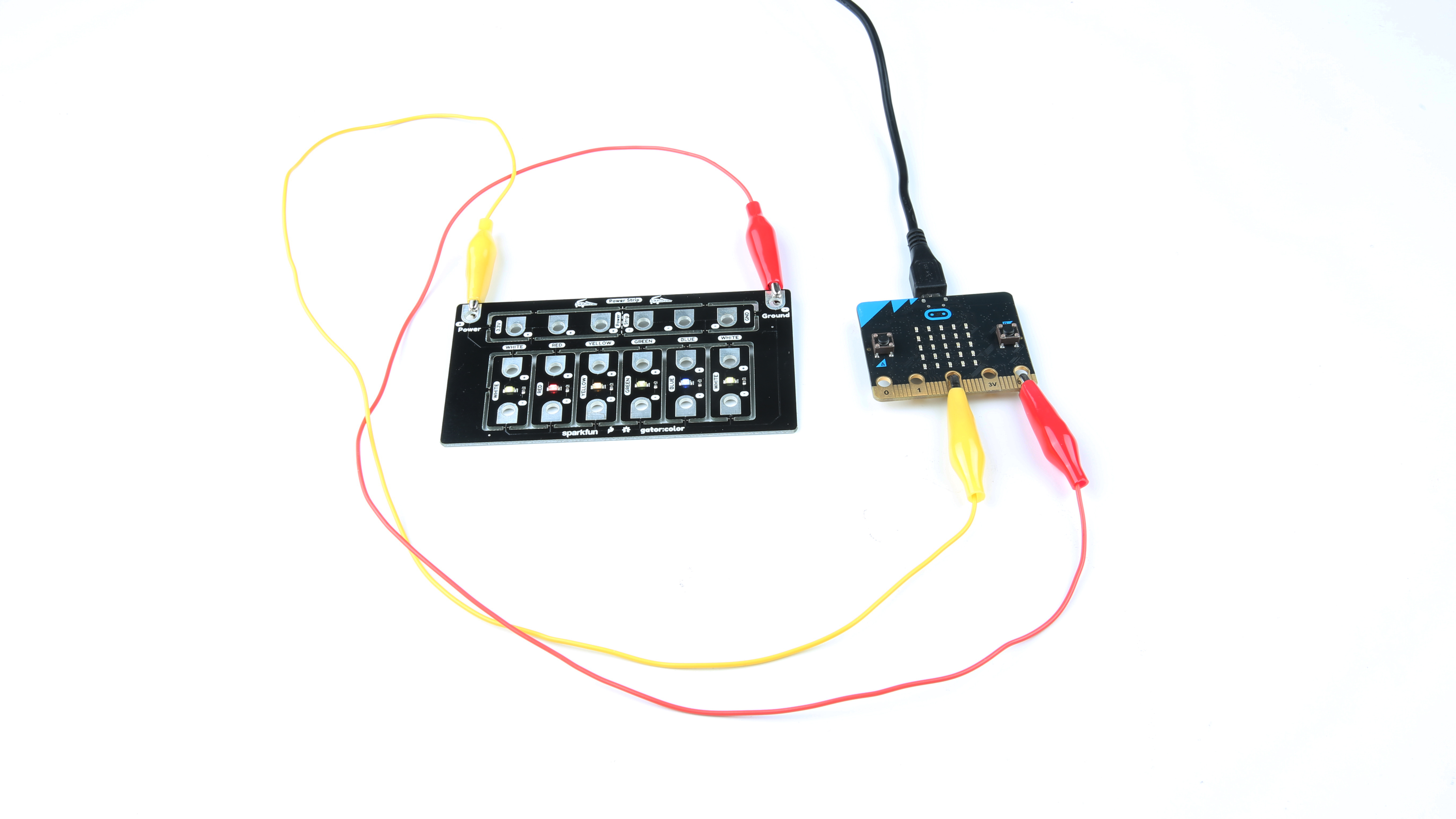
Let's start by simply turning the LEDs on. Using your alligator clips, connect the - side of the LED to ground on the micro:bit and connect the + to 3.3V on the micro:bit. You should see all of the gator:color's LEDs light up. This type of setup is shown in the photo below.
Click on the image for a closer look
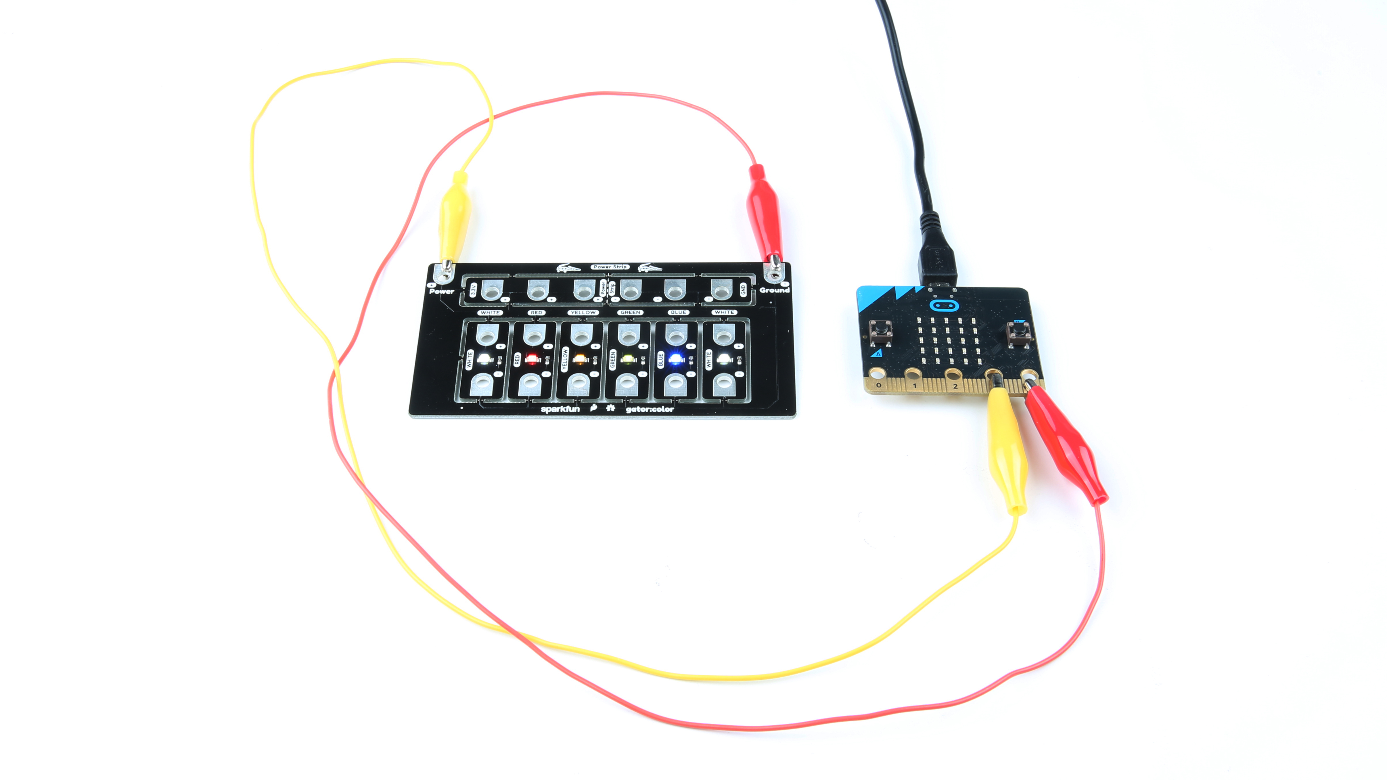
If you want to dim the LED or control it with the micro:bit, you can connect the + on the LED to any of pins 0, 1 or 2. LEDs are either on or off, with no brightness in between, so we control brightness by turning the light on and off very fast in a process known as PWM. Connect your pins as you see in the image below and we'll go over the code necessary to dim your LEDs in the next section.
Click on the image for a closer look
⚡Using with the gator:bit If you are using the gator:bit v1 (with the power switches and JST connector), keep in mind that you'll have to use pins P15, P14 or P13 to drive your LEDs, as the protection circuitry on the rest of the gator:bit pins does not create a high enough voltage to drive some colors of LED.