Fuse Breakout Board Hookup Guide
 bboyho
Hardware Overview
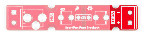
VIN
On the left side, we have our input VIN. You can solder 2-pin screw terminal (5mm) on the input side (highlighted in yellow). Or you can solder a barrel jack for the input (highlighted in black) if you decide that you want to easily connect a wall adapter (with a center positive barrel jack) for a polarized connection.
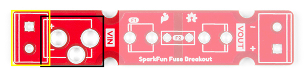
Keep in mind that the 5mm screw terminal is rated for more current compared to the barrel jack contacts. However, DC wall adapters sold from the catalog use barrel jacks to provide power. You can also solder wires directly to the breakout board as long as they are rated appropriately for the project.
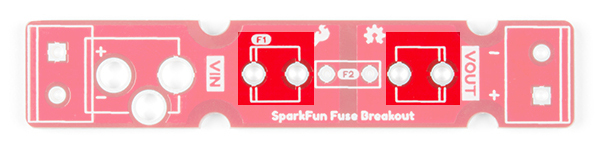
Glass Fuse
The fuse breakout board has been tested up to a 5A glass ferrule fuse.
There are two clips that will need to be soldered to the board if you are using a glass cartridge fuse. Make sure to solder the clips correctly.
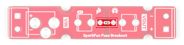
PTC Fuse
Through holes for a PTC fuse was added in case you decided to use a resettable PTC fuse. While the board was designed for a through hole PTC, you can solder still solder a SMD PTC fuse to the pads when prototyping. The component just may not fit as snug depending on the size of the SMD fuse.
VOUT
On the right side, we have our output VOUT. You can solder a 2-pin screw terminal (5mm) here.
Mounting Holes
There are four mounting holes on the board if you decide to mount the board to a panel or in an enclosure. To ensure that the board size is reduced to a minimum, half of a mounting hole was included.
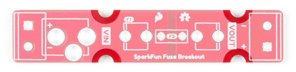
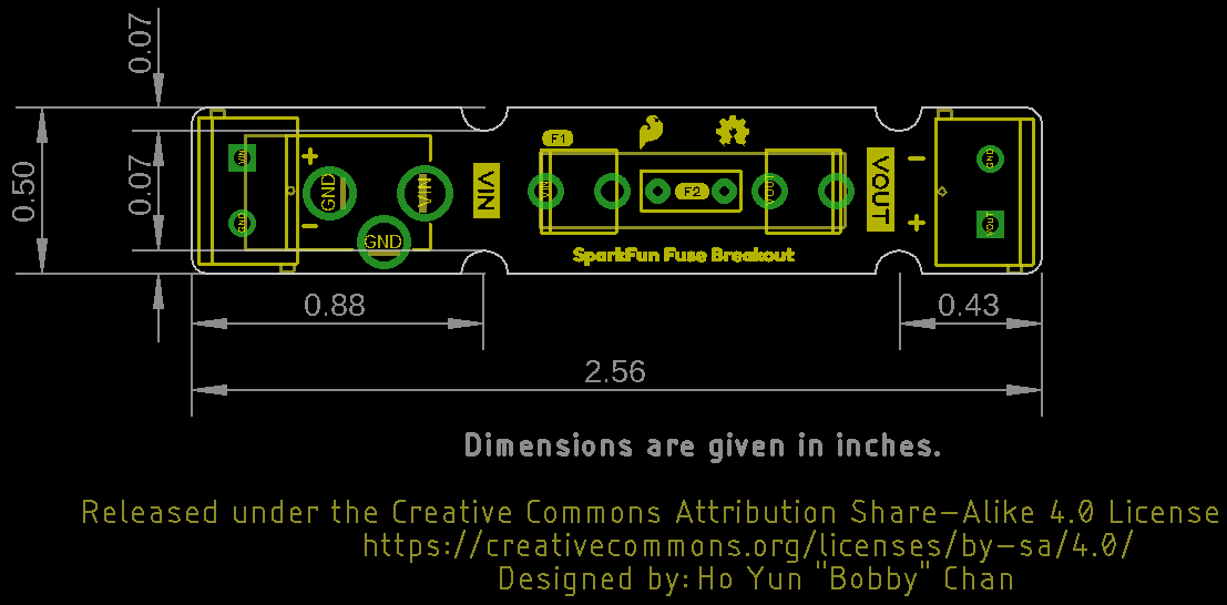
Board Dimensions
The board is 0.50in x 2.56in. There are four semi-circle mounting holes should you decide to mount the board or place them side by side.