Fuse Breakout Board Hookup Guide
 bboyho
Hardware Assembly
You'll need to solder your connectors and fuse clip to the breakout. You can solder the components in any order that you would like. If you have not soldered before, check out our tutorial below for tips!
How to Solder: Through-Hole Soldering
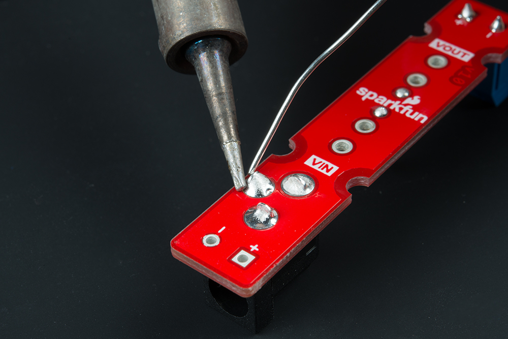
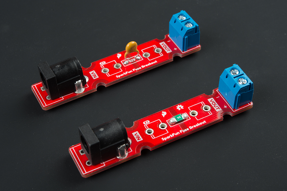
Solder Input and Output Connectors
On the VIN side, you have two options. For those that are using this with wall adapters with a center positive barrel jack, you'll want to use it with a barrel jack connector. Otherwise, you can solder 5mm screw terminal on the VIN side.
 |
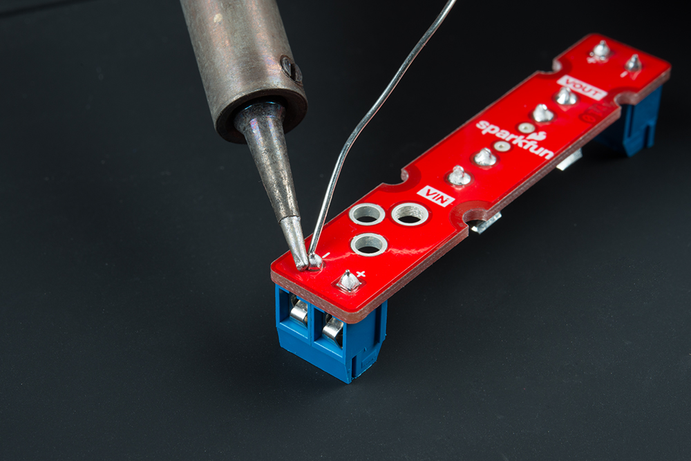 |
| Barrel Jack for VIN | 5mm Screw Terminal for VIN |
Once you have the input soldered, add the screw terminal to the VOUT side.

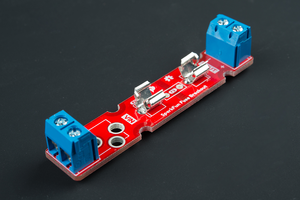
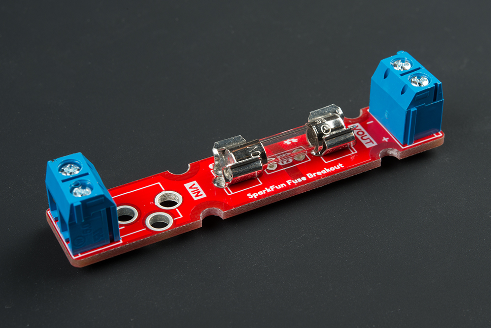
Solder 5mm Fuse Clips
The next step is to solder the glass fuse's clips to the board. Insert the clips to the each side. You'll need to make sure that the clips are oriented correctly before tacking each leg down to the board. If you look closely at the silkscreen for each fuse clip, you will see one side of the square has a secondary line added. This is the side you should orient the curved bits towards. Once each leg is tacked down, solder the other leg down. The clips can get hot when soldering so you may want to tape it down against the board or use a small piece of cardboard to hold the clip against the board.
Adding a Fuse to Your System
If you are using a glass fuse, you can now insert the glass cartridge into the clips. Should your fuse blow out, just grab a flat head screw driver and carefully pry it out.
Otherwise, insert a barrel jack into VIN side or tighten the screws to hold down stripped wires between your power supply and load. Make sure to take note of the silkscreen for your voltage and ground wires.
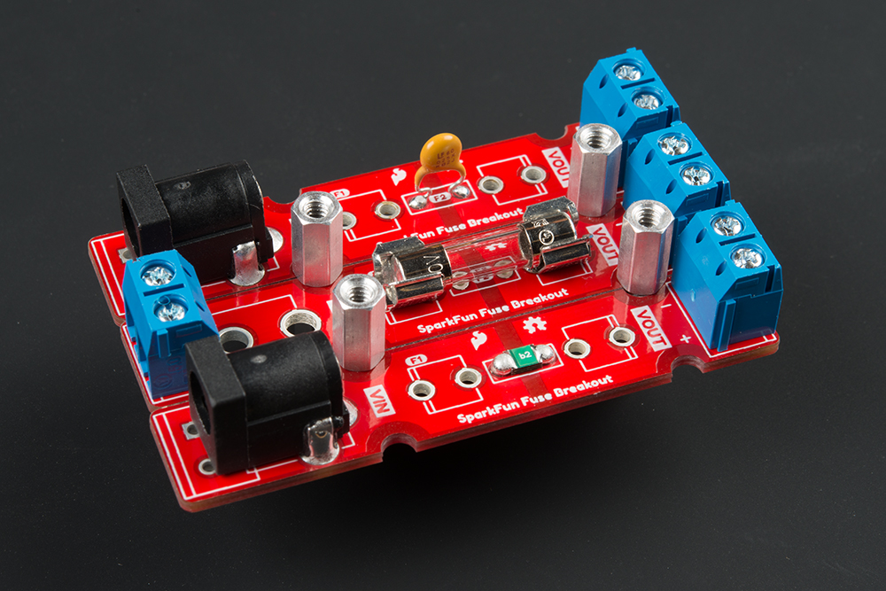
Mounting
Part of the design includes semi-circle mounting holes. This is useful if you decide mount the board to a panel or enclosure. To mount, you will need to:
- tighten some standoffs (or a screw and standoff)
- ensure that there is room to slide the PCB(s) between the hardware
- place the PCB between your standoffs to tighten
- if you are using more than one fuse breakout, place the standoffs between the two PCBs before tightening
- repeat for each standoff