FreeSoC2 Introduction
This Tutorial is Retired!
Note: This guide is for the previous version of the FreeSoC2, V11. If you have an newer version (the version number can be found on the back of the PCB), please refer to this tutorial.
View the updated tutorial: FreeSoC2 Hookup Guide V14
 SFUptownMaker
 Using the Arduino IDE
Adding Support for the FreeSoC2 to the Arduino IDE
There are two options for adding support to the IDE: you may either download the files directly and manually install them or you may use the Board Manager feature. Either way, the first step is to use the Board Manager to add support for the ARM processor core.
We're working to add the support files to the board manager, but for now, manual installation is the only option.
Adding ARM processor support
Unlike "true" Arduino boards like the Uno or Leonardo, the PSoC5LP uses an ARM Cortex-M3 processor core. Late model boards, such as the Due and the Zero, also use ARM processors, so the Arduino team have added the ARM-GCC toolset to the officially supported toolchain. That's good for us, because it means we don't have to do much work (at least, on the toolchain) to add support for the PSoC.
All you need to do is open the Arduino IDE and launch the board manager (see image below).
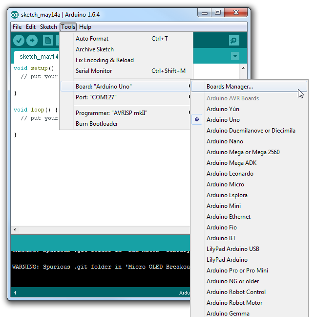
One of the by-default available options is "Arduino SAM Boards"; these are boards using the ARM Cortex processor (specifically, the Atmega SAM parts). Simply click in that box, to highlight it, and click "Install".
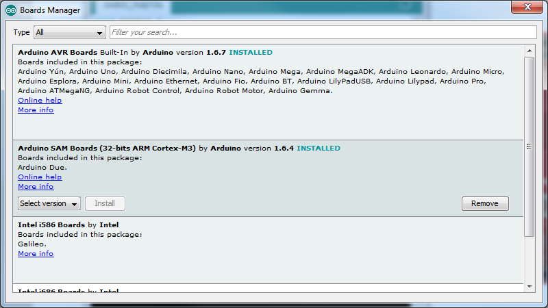
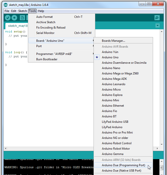
Once the install is complete, you'll see a new subgroup in the boards menu for the Arduino ARM boards. Now it's time to add support for the PSoC.
Adding Support for PSoC Boards
Manually adding support
To add support manually, you'll need to download the files from the GitHub repository.
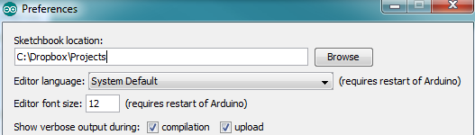
Download the support files as a zipOnce you've got your copy downloaded, all you need to do is copy the "Hardware" directory into either your sketchbook (you can find your sketchbook path in the preferences window, in Arduino) or into the main install directory for the Arduino IDE. Either way, if there's an existing "Hardware" directory, the files should just install alongside the existing files.
The other files in the folder are the PSoC Creator IDE project files for the implementation of the Arduino hardware and core software. Once you're comfortable with using the FreeSoC2 in the Arduino IDE, you may wish to open this up as a first step towards using the full features of the part.
If there isn't a "Hardware" directory in the sketchbook, that's fine; just drag the "Hardware" directory from the zip archive into the sketchbook.
Restart the Arduino IDE, and you should see the boards in the "Boards" menu.
Using the Boards Manager
At this time, we aren't supporting the boards manager for the FreeSoC2. Check back soon; we're actively working on it.
Programming the FreeSoC2 Board With an Arduino Bootloader
If you've purchased an early version of the FreeSoC2 (V11 or earlier; look on the back of the board, under the power connector for the version number), or if you've previously used the PSoC Creator software to develop on your FreeSoC2 board, you'll find that it will not respond to the bootloading commands of the Arduino IDE.
You'll need a Windows computer (at the moment; we're working on a Mac/Linux solution for the near future) to program the part with the bootloader hex file.
Download the PSoC Programmer softwareOnce you've installed the software, follow these instructions:
- Plug the board into your computer, connecting via the "Debugger" port (item 3 on the left-half hardware tour picture). Do not connect to the "Target" port at this time.
- The drivers for the KitBridge programmer/debugger (onboard the FreeSoC2) have already been installed as part of the Programmer installation. If Windows fails to detect them automatically, they can be found in the Programmer installation directory. If you have Windows 8 you may want to check out this tutorial about installing unsigned drivers.
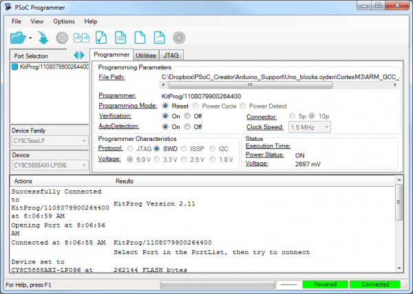
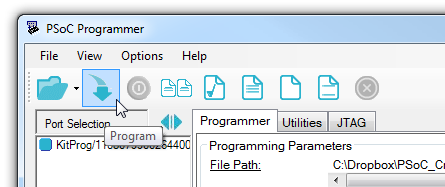
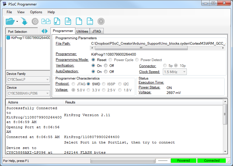
- Launch Programmer. You'll see this window:
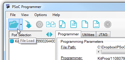
- Load the "Bootloader.hex" file, located in the support package you downloaded above ("Hardware/SparkFun/psoc").
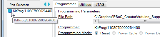
- Click the "KitProg" entry to select the board for programming. If there is no "KitProg" entry in the menu, check to make sure the driver has finished installing. If you aren't able to select the KitProg, check to make sure there isn't another copy of Programmer (or PSoC Creator, perhaps) running in another window.
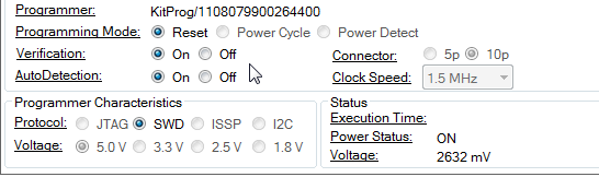
- Select "On" for both "Verification" and "AutoDetection".
- Click the "Program" button to load the bootloader onto the board.
- Connect the "Target" USB port on the board. The driver can be found in the support package you downloaded above ("Hardware/SparkFun/psoc").
If all has gone well, you'll have a new com port (named "Cypress USB UART"), and if you open the serial monitor in the Arduino IDE and send "H" and "L", you should see the LED on the board toggle.