FreeSoC2 Introduction
This Tutorial is Retired!
Note: This guide is for the previous version of the FreeSoC2, V11. If you have an newer version (the version number can be found on the back of the PCB), please refer to this tutorial.
View the updated tutorial: FreeSoC2 Hookup Guide V14
 SFUptownMaker
Getting Started with PSoC Creator
If you want to move beyond the basics, you'll need to install Cypress's PSoC Creator IDE. It's free, with no code size limitations, although Cypress does ask that you register before downloading.
It is, sadly, Windows only.
We'll go through a very simple project here, just a step more involved than a normal "blink" example.
Connecting the Board
For programming and debugging within PSoC Creator, you'll need to connect the board via the "Debugger" USB port. Driver should have been installed as a part of the Creator install process; if not, you can find them in the Creator installation directory. If you find driver installation problematic under Windows 8, we have a tutorial to help with that.
There's no need to connect the "Target" port, unless you are actually creating a project that uses USB, and that's beyond the scope of this tutorial.
Creating a Project
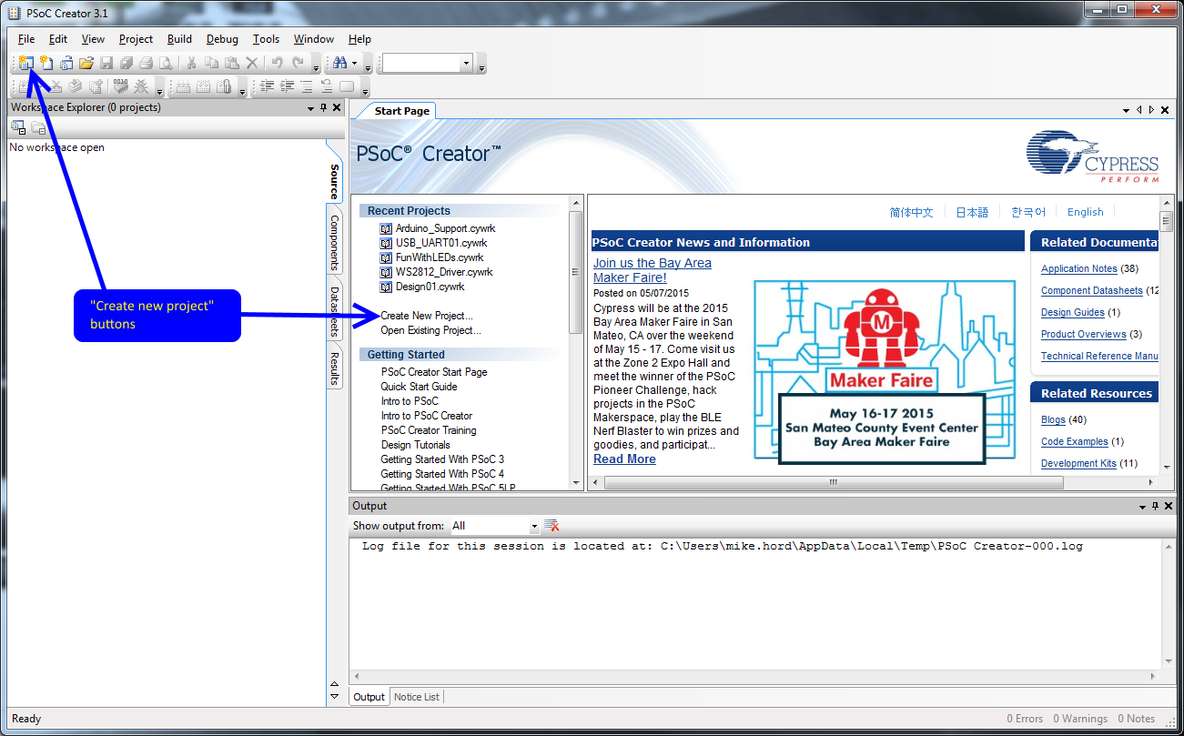
This is what you'll see when you launch Creator. To start a new project, you can either click the "Create New Project..." link on the Start Page, the "New" button in the menu bar, or open the "File" menu and choose "Project..." in the "New" submenu.
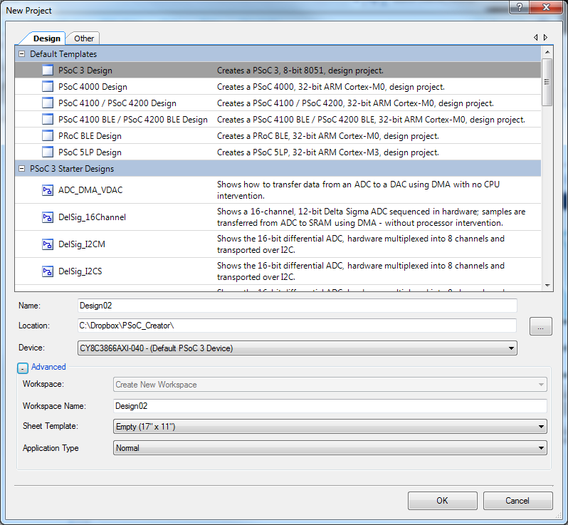
That will open this window. I've clicked the '+' next to "Advanced" to show more choices.
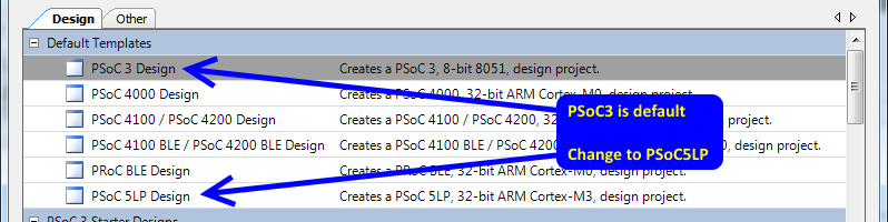
The first thing to do is to select "PSoC 5LP Design" from the "Default Templates" list. This will set up some things for you, including setting compiler options and paths.
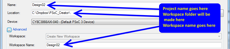
The "Name" field is the name of the project. PSoC Creator organizes applications into workspaces which contain one or more projects. For instance, you may wish to have an application and its bootloader as part of one workspace, to keep them related.
Down below that "Advanced" fold you'll see a couple of more options related to project and workspace management. If you currently have a workspace open, you have the option (via the "Workspace" drop-down) of electing to add this project to that workspace. Otherwise, it will be greyed out and you'll need to provide a workspace name.
The IDE will create a new directory with the workspace name in the directory specified in the "Location:" field; it will create a subdirectory in that directory with the name of the project (as declared in the "Project:" field).
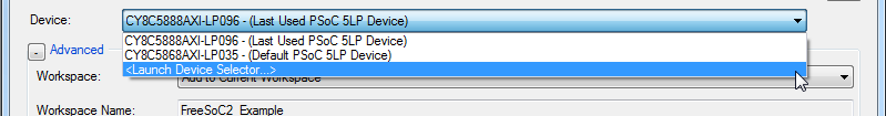
In the "Device" menu you'll find an option to launch the device selector.
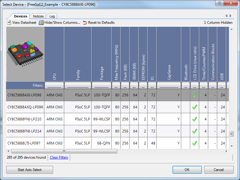
This pulls up a list of all the various PSoC5LP parts. Find the CY8C5888AXI-LP096, highlight the line, and click okay. You'll probably never need to change this again; Creator remembers the parts you've used in the past.
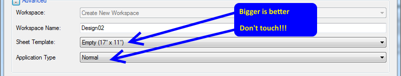
"Sheet template" is the size and format of the schematic capture sheet you'll use to define the hardware components of your design. I've selected 11"x17" ledger size, and that's a good place to start until you've gotten accustomed to breaking projects up into smaller chunks and making components in libraries.
Finally, you have the option to select whether your application is a bootloader, is bootloadable, or is a multi-app bootloader (to provide fail-safe operation). We'll leave that at "Normal" for now.
Click "OK" to move to the next step.
Adding Hardware
Before you can go any further, you'll need to add some sort of hardware to the schematic. As you add hardware elements to the schematic, the IDE will generate API files to support the hardware.
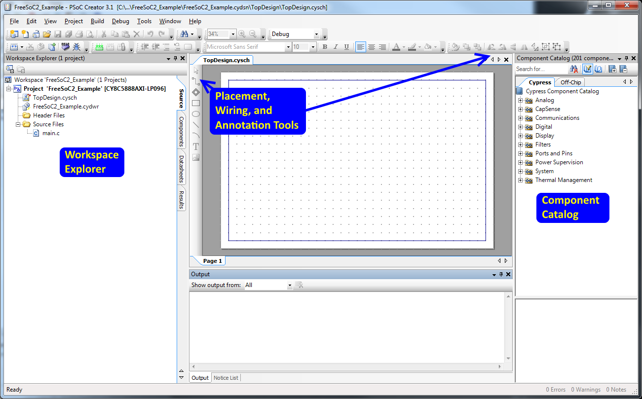
On the right side of the screen, you can see a tree-structure frame called the "Component Catalog". These are all the various hardware devices you can have the IDE build out of the chip's resources. The "Cypress" tab contains active devices, which will actually be created, and the "Off-Chip" tab allows you to add things like swtiches and LEDs. Take a moment to review the available components. There's a lot of really good stuff in there, that would normally either require off-chip resources or a great deal of resource-hogging code to implement.
On the left is the "Workspace Explorer", a tree view of the files included in the projects included in this workspace. The active workspace (i.e., the one that builds/programs when you just click the "Build" button in the shortcut bar) is bolded. Note that, although there are "folders" in this listing, those folders have nothing to do with the actual location of the files!
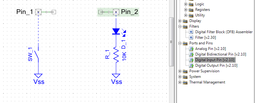
I've pulled a couple of components over from the component catalog, here: from "Ports and Pins", a "Digital Input Pin" and a "Digital Output Pin", and from the off-chip portion, a switch, resistor, and LED. Again, those off-chip parts are purely aesthetic and have no more effect on the generated output that if you were to draw a picture of a butterfly on the schematic.
To wire them up, either select the "Wire" tool on the left edge of the schematic window or press the 'w' key.
Double click Pin_1, the input pin. You'll get the component configuration window, where you can set all the various parameters that define the part at build time.
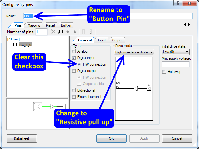
From here, you can do an awful lot. For now, we're going to do three things: rename the pin, change the drive mode to "Resistive pull up" and clear the "HW connection" checkbox. "HW connection" provides a place to attach a component internally; for example, a PWM output or an input to a counter. If you don't want to attach something to it, you have to disable this checkbox or the IDE will complain.
Rename the pin, too; the pin's name is important, as it will dictate the name of functions that the IDE will generate to provide a code interface to this object.
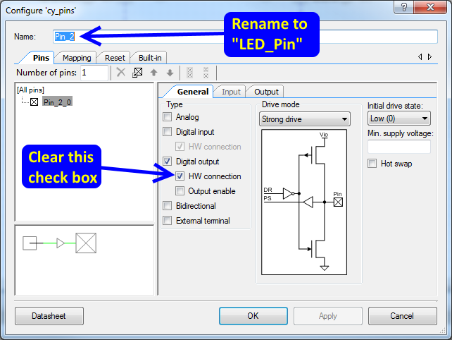
We'll do the same thing for the output pin, except here we can leave the drive mode as-is.
One other thing to notice here is the button in the lower left: "Datasheet". Each of these components has a very well written datasheet describing what it does, what every setting in the configuration window if for, how to use the API, and how much of your available digital or analog resources you can expect it to consume.
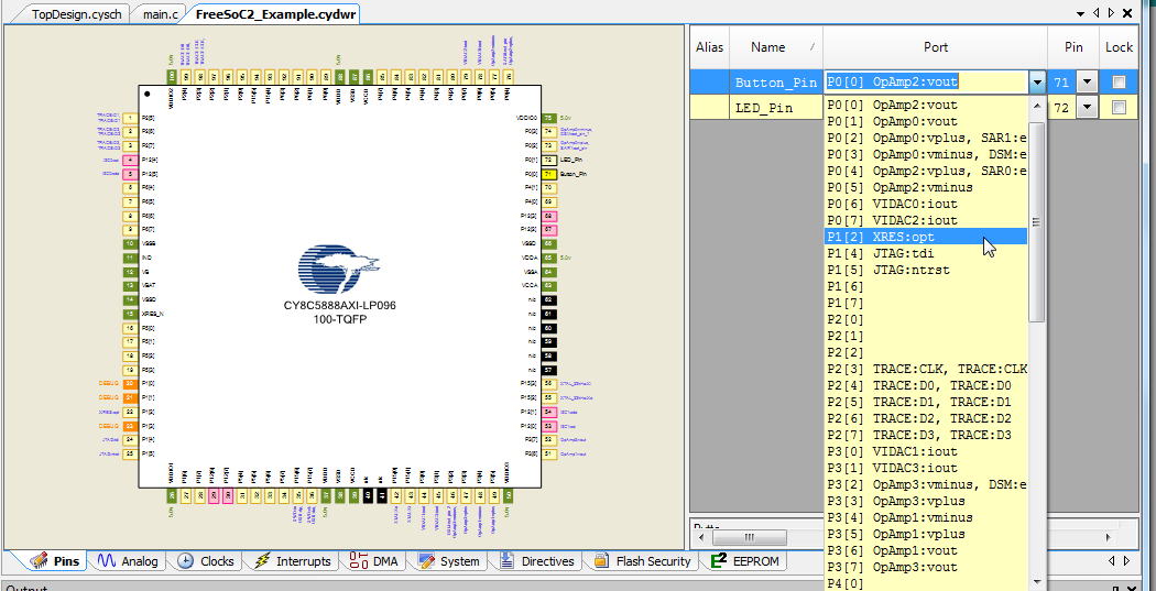
The last thing to do before we can write some code is to assign these logical pins to a physical pin on the package. To do this, open the .cydwr file from the workspace explorer on the left side of the window. You'll get something that looks like this:
Ignore the tabs along the bottom edge for now.
On the right side, there's a list of pin objects, port pins, and physical pin numbers. If you don't assign a pin to a physical port, the IDE will do it for you. On the FreeSoC2, the user button is attached to port 1, pin 2, and the user LED to port 6, pin 7, so let's make those assignments now. Note how the "lock" box becomes checked when you change the setting; that prevents the IDE from reassigning that pin.
You'll also notice that many pins have some extra text associate with their port/pin information; for example, P1.2 is also labeled as "XRES:opt". These are special functions that can be associated with the pin for improved performance, rather than mandates that a given pin be used for a specific function.
Code!
Let's write some code!
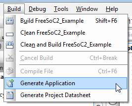
The first thing to do is to create the necessary API files to support the hardware you placed in the schematic earlier. To do that, choose the "Generate Application" item in the "Build" menu.
You'll note that a bunch of new files pop up in the workspace explorer. These are the support files for the components. Don't edit them. They are, in fact, just standard C files, and you could rework them to fit your needs, but the IDE can, and does, frequently regenerate those files, which would wipe out any changes you've made.
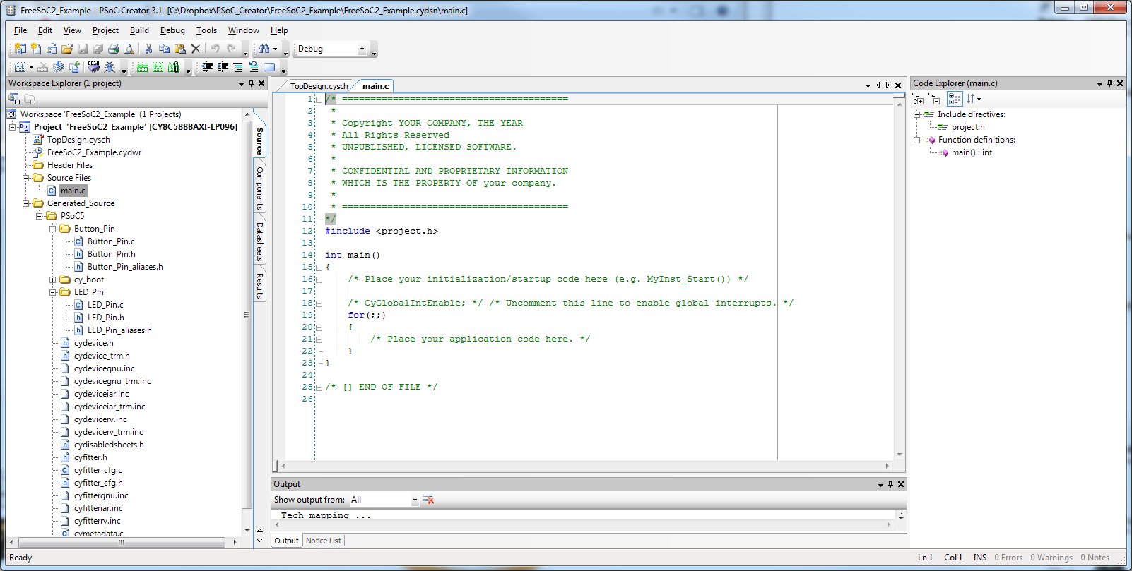
Here's our main.c file. This is automatically generated, and you can safely alter it without worrying about the IDE breaking it.
Put this code into the for(;;) loop section:
if (Button_Pin_Read() == 0)
{
  LED_Pin_Write(1);
}
else
{
  LED_Pin_Write(0);
}
It's pretty simple: turn the LED on when the button is pressed and off when it's released.
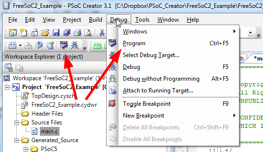
Now you can upload the code to the processor. The big red arrows in the picture below show three ways of doing it: a menu item in the "Build" menu, a button on the menu bar, and CTRL-F5 as a hotkey. Make sure that you're connected to the "Debug" USB port! The "Target" port can only be used for uploading code via a bootloader.
The IDE will automatically save all open, changed files, and initiate a rebuild if necessary. Then, it will find any attached programmers and automatically connect and program.
Hardware!
This is the PSoC, though, right? So, we can skip the code part, entirely!
Delete the code you just added to the main.c file, and let's do it in the schematic instead.
Open up those pin configuration windows again, and this time check the "HW connection" checkboxes. If you don't do this, you won't be able to connect the pins to one another.
Then, add a piece of wire (the wire tool can be activated by typing "w" or with the toolbar on the left edge of the schematic) between the little boxes that appeared on those pin symbols, like this:
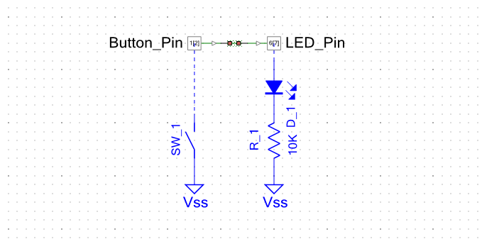
Now, click that "Program" button again and let's see what happens...
Whoops! The light is off when the button is pressed and on when it's release! The polarity's reversed. We need an inverter. Find the "Not" component in the Component Catalog, under Digital/Logic. Don't forget to delete the wire between the two pins before connecting the inverter!
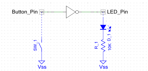
Ah! There we go. Now it works right, and it required no code at all, nor any changes to the physical hardware outside the device.
Keep going!
There are a lot of examples provided with Creator; they can be added to an existing workspace from the "Examples..." menu item in the "File" menu.
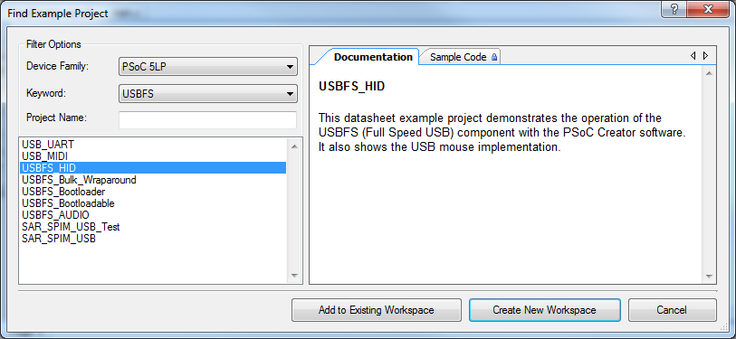
Examples are sorted by keyword; there's an example for almost every problem.