FLIR Lepton Hookup Guide
Contributors:
 Nick Poole
Hardware Hookup
⚡ Warning: It is worth mentioning that while the Lepton module isn’t particularly sensitive to electrostatic discharge, it is a complex and relatively pricey component. You might want to take a few precautions while working with it so you don’t accidentally zap it.
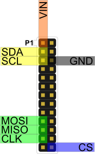
Circuit Diagram
Connect the FLIR breakout to the Raspberry Pi GPIO according to the diagram below. If you need a refresher on how the GPIO pins are oriented, visit our Raspberry Pi GPIO tutorial. Make sure that your Lepton module is securely snapped into the socket on the breakout board.
Heads up! If you have issues getting the camera to work (i.e. you see a red square and no image) with pin 26, you may need to adjust the CS pin to pin 24 (next to the CLK pin) like this tutorial from FLiR.
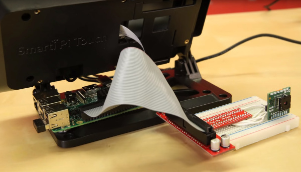
There are several methods of connecting and mounting your system together. If you used a breadboard and LCD touchscreen with the Pi, your setup should look similar to the image below.
Congratulations, that’s the hardware part done. Now onto the software configuration!

