Flashlight Kit
 M-Short
Flashlight Circuit
The Circuit
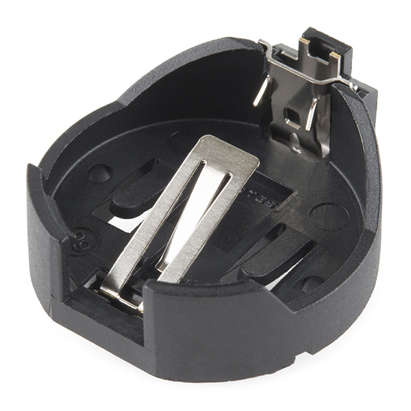
So, what does our circuit do? A completed circuit is a path where electrons can flow. Consider the battery our source of electrons. Current is how we measure the flow of those electrons. Starting with the positive end of the battery, you can see the path it takes along the left side of our PCB up to the resistor. Batteries are basically our power house that stores power and outputs that power in terms of current (how fast the electrons are moving) and the voltage (the amount of pressure pushing those electrons through the circuit).
 |
 |
| Battery Holder | Schematic Notation for Battery |
The Resistor
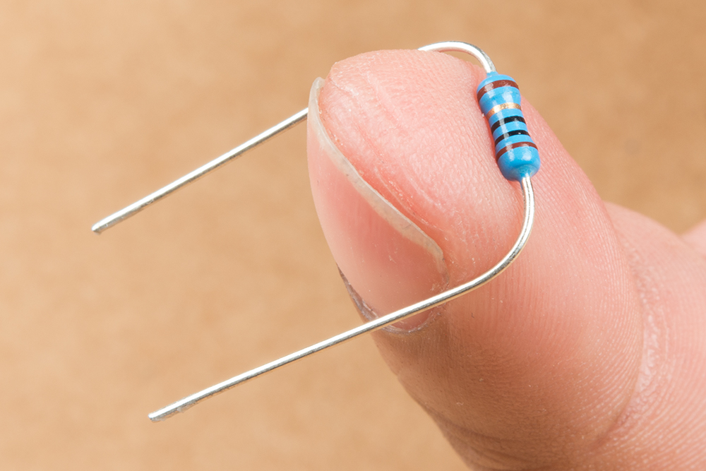
The resistor is like a tube that restricts the amount of current that can get through. This resistor minimizes the current that gets to your LED so we don't give the LED too much current and destroy it. If you are curious how this works you can check out our LED tutorial to see how to properly size a resistor. If you look closely at your resistor you'll notice some color bands. In this kit we use a 5 band resistor (brown, black, black, gold, brown); this is a 10 Ohm resistor with a 1% tolerance. Resistors are not directional, meaning they can be used in the circuit in either a forwards configuration (brown, black, black, gold, brown) or a backwards configuration (brown, gold, black, black, brown) and still function correctly.
 |
 |
| Resistor | Schematic Notation for Resistor |
The LED
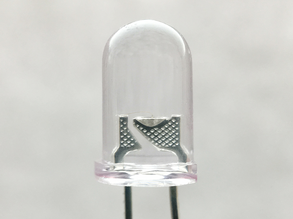
Next we have the LED. LED stands for light emitting diode. A diode is 2 pieces of semiconductor placed together to allow current to only flow in one direction. This is one of the reasons your LED is polarized (meaning it matters which way you hook it up). The current can only flow from the positive side (anode) to the negative side (cathode). In this case we are using a light emitting diode, which does exactly what it sounds like. It is a diode that emits light which is very convenient for a flashlight. Using different substances in the diode allow for different colors; for our flashlight we chose a white LED.
 |
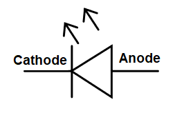 |
| LED | Schematic Notation for LED |
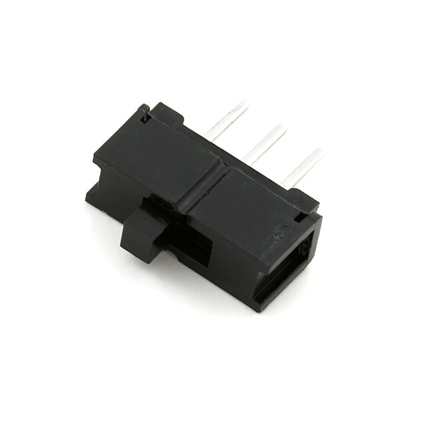
The Switch
Last we have our switch. A switch is actually a mechanical part, meaning you have to physically move the switch Physically moving the switch will connect the negative pin from your LED to the negative pin of your battery, thus completing the circuit. Flip the switch the other way and the switch physically disconnects those 2 components.
 |
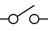 |
| Switch | Schematic Notation for Switch |
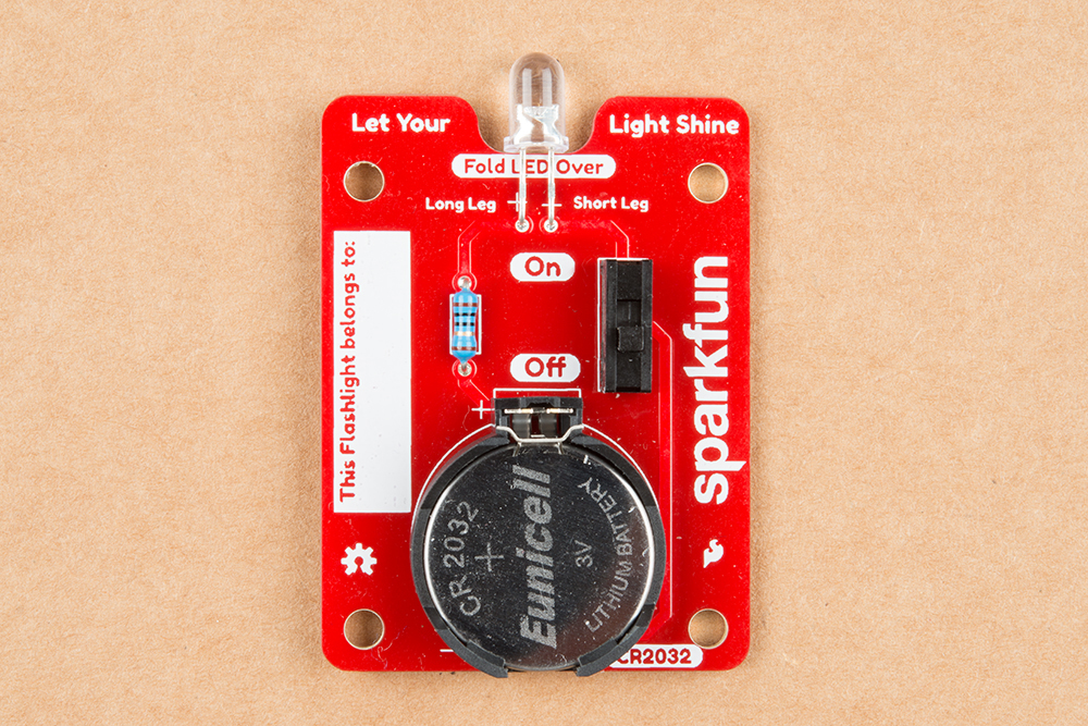
The Schematic
Once you put everything together, our electrons will flow (when the switch is in the On position) and our flashlight will turn on. Here is a picture of the completed board and the full schematic (also found on the back of the PCB).
 |
 |
| Completed Flashlight | Schematic Notation for Completed Circuit |