Fading with the MOSFET Power Switch and Buck Regulator
 Christo-boots with the-pher,
  bboyho
Fading
In this example, we will slowly turn on the load and then slowly turn it off using the N-channel MOSFET. This example is better with a DC motor and 12V LED. You will typically want the solenoid to be fully turned on/off.
For this example you will need the SparkFun IoT RedBoard - ESP32 Development Board, a USB-C Cable, the SparkFun MOSFET Power Switch and Buck Regulator (Low-Side), a Mini Screwdriver, M/M Jumper Wires, an RGB LED Strip, and a [12V Wall Adapter Power Supply](12V Wall Adapter Power Supply).
Hardware Hookup
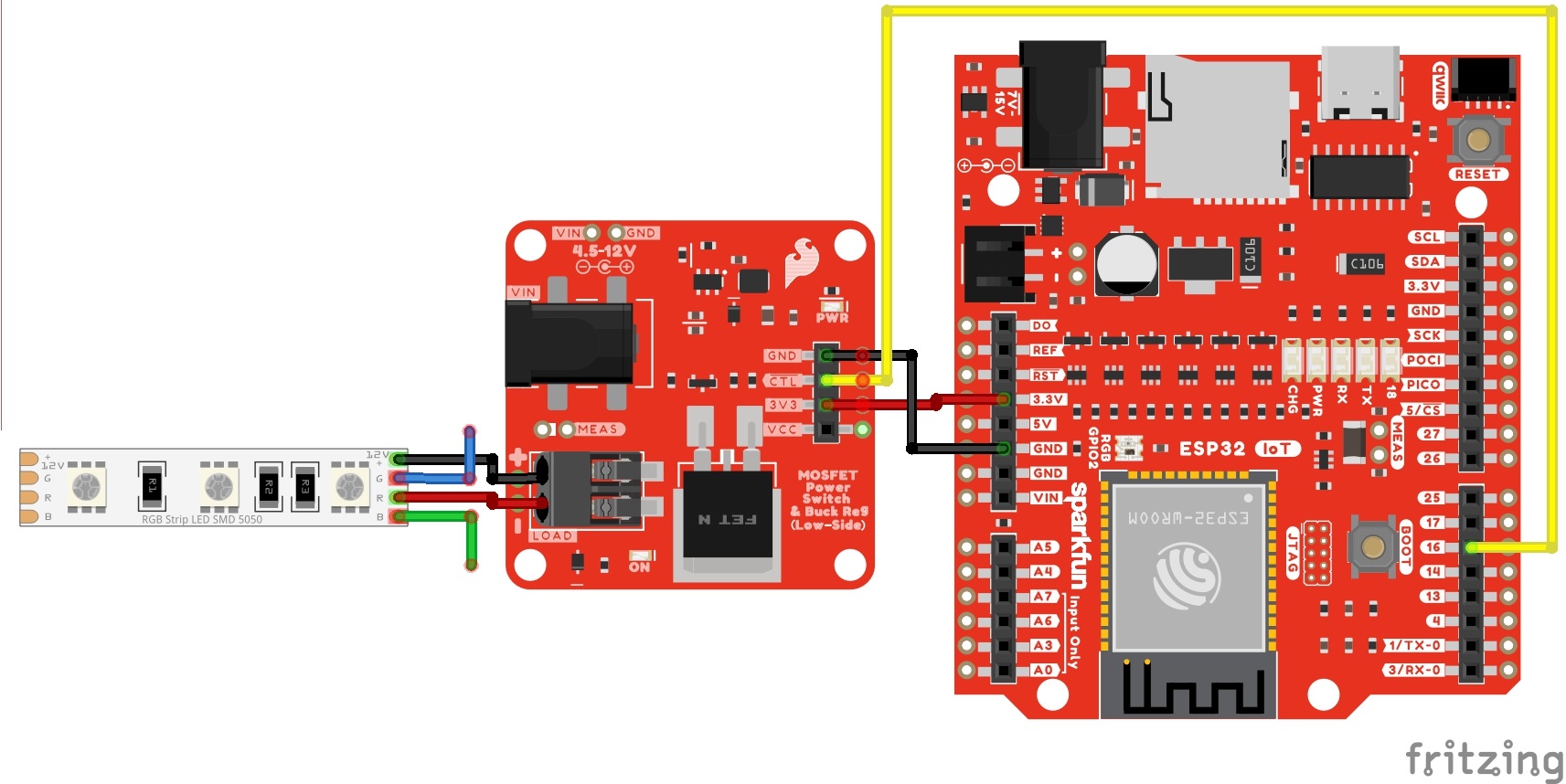
You will need to connect everything as explained earlier. For this particular example, we will use one channel from a 12V RGB LED strip as shown in the circuit diagram below.
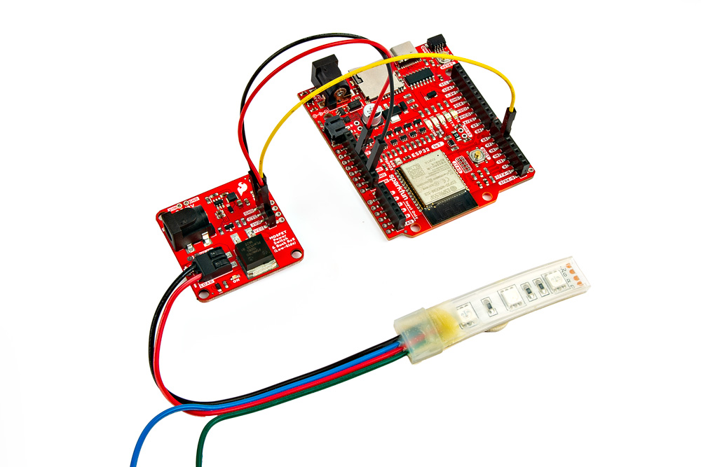
Your setup should look similar to the image below without the power supply.
Upload Code
To upload code, insert the USB cable into the IoT RedBoard - ESP32.
Copy the following code and paste it in the Arduino IDE. If you have not already, select your Board (in this case, the SparkFun ESP32 IoT RedBoard), and associated COM port. Then hit the upload button.
/******************************************************************************
  Example: Fading
  Modified By: Ho Yun "Bobby" Chan
  SparkFun Electronics
  Date: October 27th, 2023
  License: MIT. See license file for more information but you can
  basically do whatever you want with this code.

  This example is based on Arduino's fade example. It has been modified
  so that it can be used for the SparkFun IoT RedBoard- ESP32 but it can be
  used with any Arduino that has a PWM pin. The load (DC motor,
  or 12V LED) will slowly turn on and off. This code will be more useful for
  users connecting a DC motor or nonaddressable LED so that you can partially
  turn on/off the load.

  Users can also open the Serial Monitor at 115200 to check on
  the status of the button for debugging.

  Feel like supporting open source hardware?
  Buy a board or component from SparkFun!

      SparkFun MOSFET Power Switch and Buck Regulator (Low-Side): https://www.sparkfun.com/products/23979
      SparkFun IoT RedBoard - ESP32 Development Board: https://www.sparkfun.com/products/19177
      Hobby Motor - Gear: https://www.sparkfun.com/products/11696
      Blower - Squirrel Cage (12V): https://www.sparkfun.com/products/11270
      12V LED RGB Strip - Bare (1m): https://www.sparkfun.com/products/12021
      Wall Adapter 12V/600mA, (Barrel Jack): https://www.sparkfun.com/products/15313

  Distributed as-is; no warranty is given.
******************************************************************************/

int loadPin = 16;

// the setup function runs once when you press reset or power the board
void setup() {

//Initialize Serial for Debugging if there is no built-in LED
Serial.begin(115200);
Serial.println("Analog fade in and out to slowly turn on/off load!");

// Set up the load pin to be an output and turn it off:
pinMode(loadPin, OUTPUT);
analogWrite(loadPin, 255);

Serial.println("OFF");

}  //END SETUP

// the loop function runs over and over again forever
void loop() {

Serial.println("<===== FADE IN =====>");
// fade in from min to max in increments of 5 points:
for (int fadeValue = 255; fadeValue >= 0; fadeValue -= 5) {
// sets the value (range from 0 to 255):
analogWrite(loadPin, fadeValue);
// wait for 30 milliseconds to see the dimming effect
delay(30);

Serial.println(fadeValue);
}

Serial.println("<===== FADE OUT =====>");
// fade out from max to min in increments of 5 points:
for (int fadeValue = 0; fadeValue <= 255; fadeValue += 5) {
// sets the value (range from 0 to 255):
analogWrite(loadPin, fadeValue);
// wait for 30 milliseconds to see the dimming effect
delay(30);

Serial.println(fadeValue);
}

}  //END LOOP
What You Should See
Once the code has uploaded, disconnect the USB cable from the IoT RedBoard - ESP32. Then insert the barrel jack from a power supply to the MOSFET Power Switch and Buck Regulator's barrel jack connector. In this case, we used a 12V wall adapter power supply.
The load will slowly turn on and slowly turn off. This will loop forever until power is removed from the board. If necessary, disconnect the 3.3V jumper wire from the IoT RedBoard - ESP32, reconnect the USB cable, and open the Arduino Serial Monitor at 115200 baud for debugging purposes.
While this example was used to turn on one channel of a 12V RGB LED strip, you could also use this example with a DC motor. Try using a potentiometer (or any 3.3V analog sensor) with the map() function to adjust the speed of the motor.