Experiment Guide for the Red Hat Co.Lab Farm Kit
 D___Run___,
  Gina Likins
Experiment 2: Building Your "Water Me" Signal
Now that you've figured out how a breadboard works, experimented with some basic circuits, and seen first hand how polarity acts as a "gate" for current, it's time to put all that knowledge to work and build your "Water-Me Signal."
Here's a complete walkthrough of Experiment 2, but we've also broken it down step-by-step below.
Building your circuit
Remove the resistor from your last circuit from Experiment 1. We won't need it for the "Water-Me Sensor" because we're adding another component, the sensor, with enough resistance that the LED will be fine. (But keep it -- you can never tell when an extra resistor will be useful).
Remove the LED also, but keep it handy, as you will be needing it. You can leave your battery where it is.
Now take a look at the sensor itself, and you will see three connections:
- VCC, which stands for Voltage Common Collector: this is where current enters the sensor.
- GND, or Ground: the zero voltage point of a circuit, which for a Direct Current (DC) circuit (like this one) is usually connected to the negative terminal (or anode) of the battery.
- SIG, or Signal: the SIG pin on most components means "signal". In this case SIG is an output pin that varies the amount of current sent in response to changes in conductivity between the sensor prongs. That's a lot of info, but for now, think of SIG as the "information out" line for the sensor.
Top side of sensor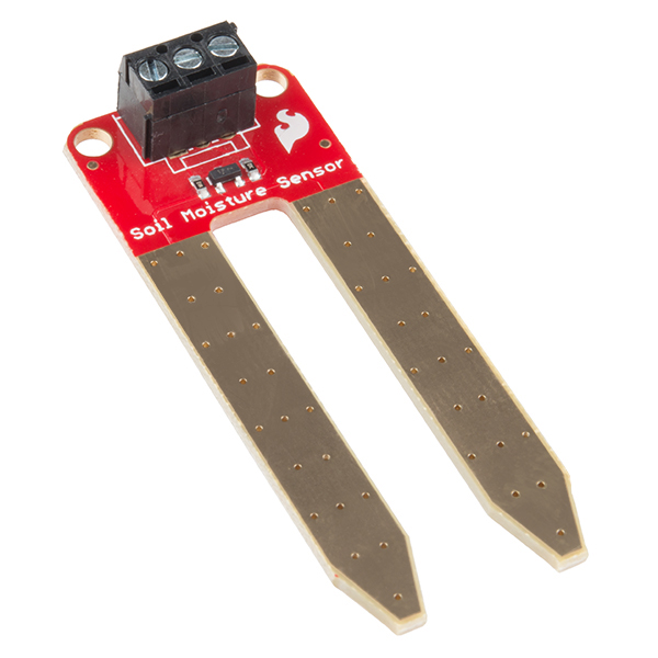 |
Bottom side of sensor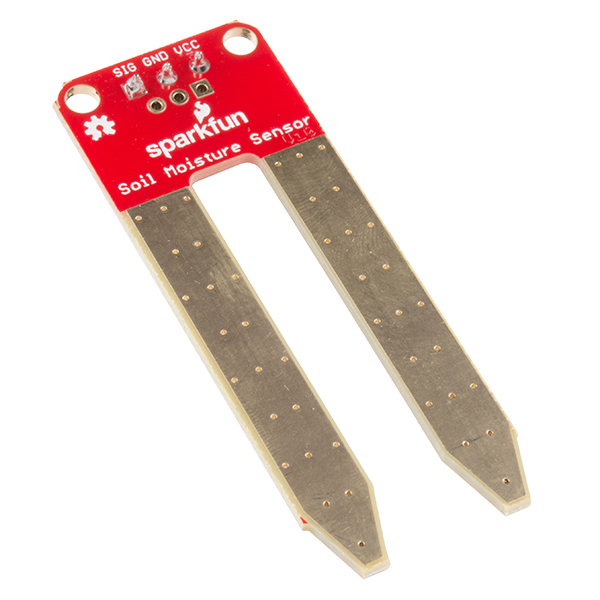 |
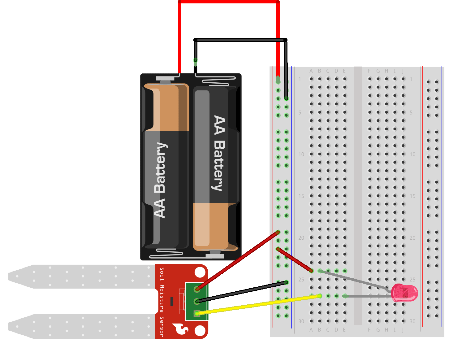
To get the sensor ready to use in your circuit, insert one end of a red jumper wire (we recommend red, but you do you -- remember, they're all the same on the inside) into the hole marked VCC and use the small screwdriver included with the kit to tighten the set screw, capturing the wire. (It doesn't have to be super-tight, just enough that it doesn't pull out easily.)
Now do the same thing two more times, putting a black jumper wire into the GND pin and a jumper wire of whatever color you want into SIG.
Your sensor should look like this when you're finished:
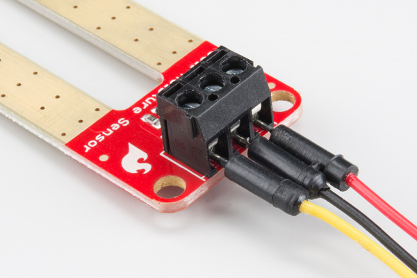
For example, I always use yellow for "SIG" -- it makes it easier to spot those "signal wires" when I'm looking at a complex circuit.
Next, insert the other end of the VCC jumper wire (which is red, if you are using the conventional color scheme) into the positive (+) power rail.
Insert the other end of the jumper wire attached to the SIG pin into any hole in any terminal strip -- your choice! Then insert the negative leg (-) of the LED so that it is also connected to the SIG jumper wire, which is yellow if you're using my color suggestions (Hint: any hole in the same terminal strip will work).
Insert the positive leg of the LED into the (+) power rail -- directly if it's close enough, or use a jumper wire in between if it's not.
Finally, insert the other end of the sensor GND jumper wire (probably black) into the negative (-) power rail.

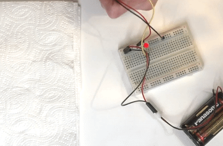
Your "Water-Me Sensor" should be lit up (because it's dry!).
Project checklist
☑ Read Requirements and Assemble Tools
☑ Read the Instructions
☑ Identify the Parts
☑ Build Your Project
☐ Testing
☐ Show it off!
Testing
To test your "Water-Me Sensor" you can use a paper towel in place of the hydroponic felt that will be in the planter. Touch both tips of the sensor prong to the paper towel -- your LED should stay lit.
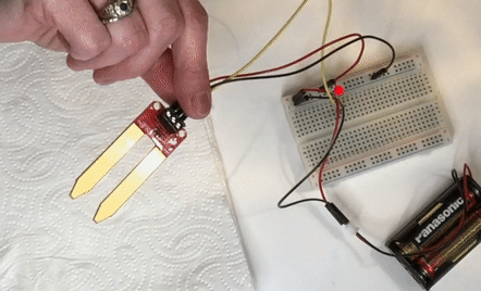
Now, take a little water and pour it onto the paper towel, then touch the prong tips to it (make sure both prong tips are touching the wet part of the towel).
Hopefully, your LED just went out (if not, check the Troubleshooting section).
Project checklist
☑ Read Requirements and Assemble Tools
☑ Read the Instructions
☑ Identify the Parts
☑ Build Your Project
☑ Testing
☐ Show it off!
That's pretty cool, but...
How does it work?
What's going on with the sensor? How does it "know" when there's no moisture?
The paper towel, when dry, is a poor conductor of electricity (most fabrics are).
But most water is a good conductor of electricity, so adding moisture increases the conductivity between the prongs, meaning more current can flow between them.
That's important because this sensor detects the amount of conductivity between the prongs and, based on that, changes the amount of current that gets sent to GND or SIG. The more conductivity there is (the more electricity can flow between the two prongs) the more current is sent to SIG (and the less gets sent to GND).
This means that when your felt is moist -- and is therefore a better conductor of electricity -- there's more current going to SIG and less to GND.
But finding perfectly pure water is almost impossible -- and definitely not something you should try in an experiment with electricity!
Reversing the circuit to see what happens
This next part is easier to understand if you see it for yourself, so let's take apart the perfectly good circuit you just finished. (I know, it sounds ridiculous, but trust me it's worth it...and we'll put it back afterwards.)
In the circuit that you built, reverse the way the LED is connected, so that the positive (+) leg (the longer one) is connected to the SIG pin and the negative (-) leg (the shorter one) is connected to ground, using jumper wires as necessary:
More conductivity between the sensor prongs causes current to get shifted to the SIG pin, so you might expect that when moisture increases the LED would light up... and, in fact, if you take the prongs of your sensor and barely touch them both to your paper-towel-with-a-puddle-on-it, that's exactly what happens.
(You've now built a moisture sensor -- people buy these to put in their basements or crawlspaces to sense water leaks! Nifty, huh?)
Back to the "Water-Me Sensor"
Before we go any further, go ahead and switch that LED back the way it was before: with the negative (-) leg of the LED connected to the SIG pin and the positive (+) leg connected to the positive (+) power rail.
To test that you've reconfigured it correctly, make sure the sensor isn't touching the wet paper towel (and that there's nothing else -- like your finger -- causing a connection between the two prongs). Your LED should be lit up (if not, see Troubleshooting).
But how does switching the "direction" of the LED turn a moisture sensor into a "Water-Me Signal" (or, to think of it another way, an "anti-moisture signal")?
In this configuration, voltage comes in via the positive power rail and goes through the LED. Remember, though, that a circuit has to be complete to work, so where is the rest of the circuit path -- where does it connect back to ground?
When there is conductivity between the prongs of the sensor, all the current goes out the SIG pin, which means there's no connection between the sensor and the GND pin. With no connection to GND, the circuit isn't complete, so the LED can't light.
But when there is no conductivity, the sensor opens the connection to GND, which means that there is now a complete circuit: the positive power rail is connected to the LED and the moisture sensor, and the moisture sensor is connected to GND.