Experiment Guide for the Red Hat Co.Lab Farm Kit
 D___Run___,
  Gina Likins
 Introduction
In this kit you’ll find everything needed to start your own open source farm.
The Red Hat Co.Lab Farm kit packs three activities into one small box:
First, learn about the way breadboards work and experiment with creating simple circuits using a breadboard, jumper wires, batteries and an LED. Breadboards are an easy way to experiment with electrical circuits, as you can test different configurations without making the connection permanent (like solder would).
Then, using the same components you used in your breadboard experiments, plus one more, you’ll create a “Water-Me Signal,” which will light up when there’s not enough moisture. The neat thing is that by reversing just one piece of the circuit, the same set of components can be used to make a “wetness” sensor that lights up when there’s too much moisture -- and we’ll figure out why.
Finally, with your addition of some microgreen seeds and a recycled container, and using the hydroponic felt that came in the kit, you can plant your own microgreen garden. Add some sun, and a few days later you will have your own crop.
Once you've planted your microgreens you can watch Red Hat’s Open Source Stories film Farming for the Future to see how farmers today are using open source tools and principles to grow food in ways that are more efficient and more ecologically friendly.
Before You Start
Before you start building your farm, there are some things that you can do ahead of time to ensure your farm project will be a success. The information below will tell you how much time you can expect to spend, what tools and materials you'll need, and what you can do before you start your project that will make it easier (and more likely to work!).
Recommended Age and Prerequisite Skills
This activity is best suited for ages 9 and up.
There are no specific skills necessary to complete the project, and no prior knowledge of circuits is assumed. Some of the components are small and making connections requires a bit of dexterity, so younger students may need adult assistance.
Time Requirements
- Experiment 1: Breadboards and Basic Circuits - 30 minutes (but there's lots of experimentation that can be done here, so feel free to spend more time with this)
- Experiment 2: Building Your "Water-Me" Signal - 30 minutes
- Experiment 3: Planting Your Farm - 15 minutes to plant (but you'll also spend time caring for your farm after you plant it)
Tools and Materials
- The Red Hat Co.Lab Farm Kit
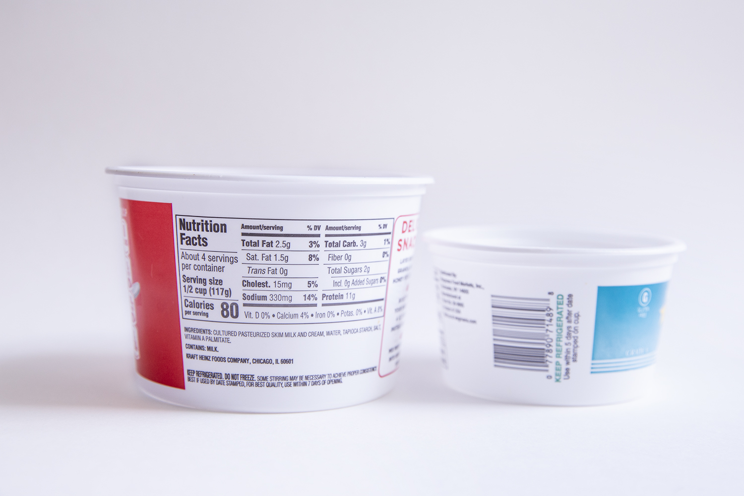
- A container: to plant your seeds in. Approximately 3-5" across (round or square is fine) and no more than 2-3" deep is perfect. A well-rinsed, recycled tub like yogurt or cottage cheese comes in; the 8 oz. size of takeout container; or a milk carton, trimmed down (with adult help) would all work well.
- Microgreen seeds: you can order these online from many places (and may be able to find them at your local garden store). You don't need many, and several people can split a single package of seeds.
- Scissors -- for cutting the hydroponic felt to fit the bottom of your container. The felt can be torn, but it shreds a little, so it's neater to cut it.
- A Pencil: to mark your felt before trimming it
- Electrical Tape: electrical tape can be used to provide extra protection for the sensor connections (not necessary, but helpful)
- A sunny spot to put your tiny farm: check the planting instructions on your seed package for light requirements, and make sure you have a suitably sunny spot picked out for your farm where you will also be able to see the "Water-Me Signal."
Project checklist
☑ Read Requirements and Assemble Tools
☐ Read the Instructions
☐ Identify the Parts
☐ Build Your Project
☐ Testing
☐ Show it off!
Read the Instructions
You know how people always say "Read all the instructions before starting?" It really does help. (Hint: try to familiarize yourself with the parts you'll be using as you're reading through the instructions.)
Project checklist
☑ Read Requirements and Assemble Tools
☑ Read the Instructions
☐ Identify the Parts
☐ Build Your Project
☐ Testing
☐ Show it off!
Identify the Parts
Before you start your project it's a good idea to check to be sure that you have everything you need (and that you know which part is which). This includes making sure that you have any required materials that didn't come in the kit (like your planter and your seeds!).
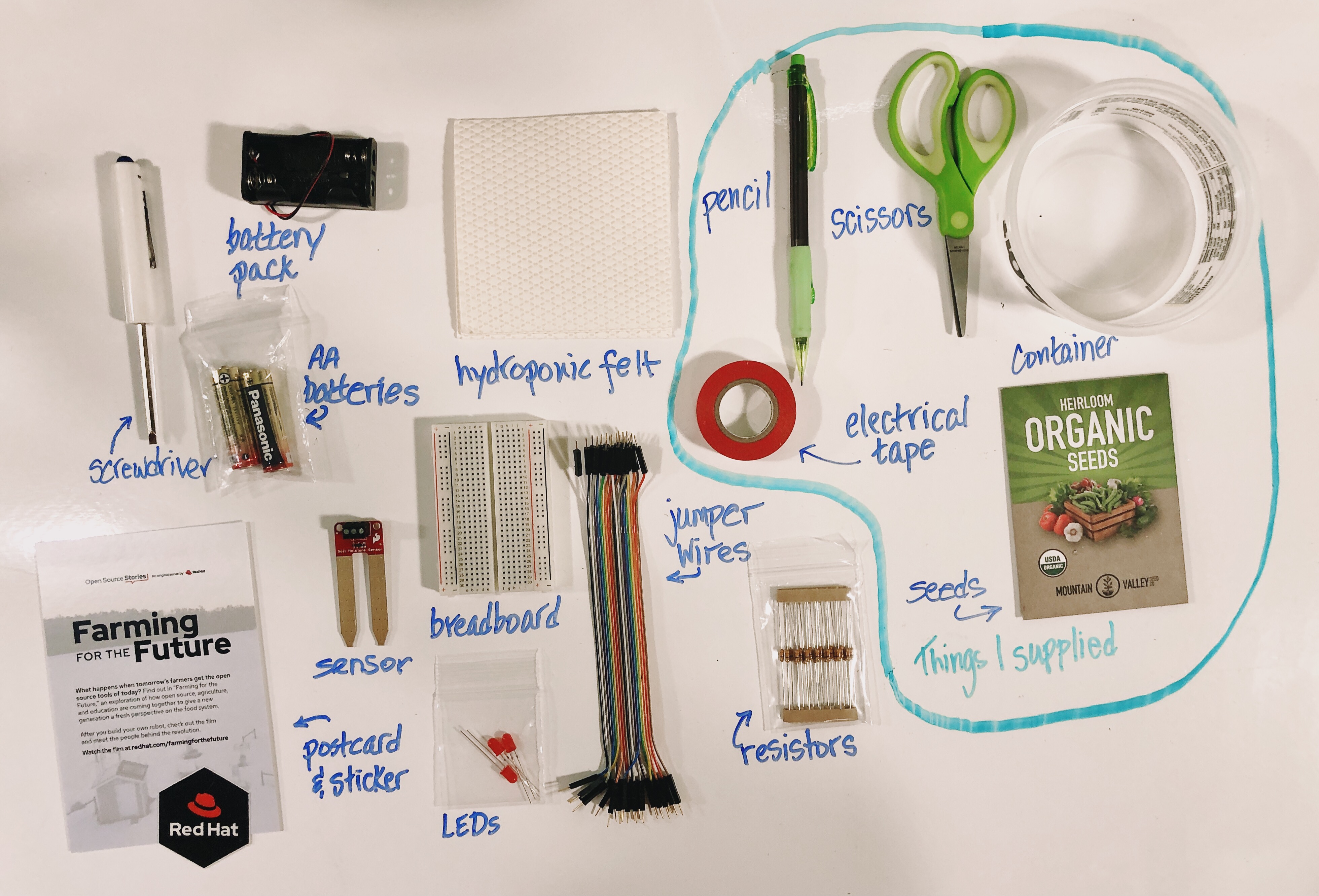
I've taken my kit and laid out the parts. As I do this I am doing three things:
- identifying each part (and labeling it so I can find it easier)
- counting each part to make sure that I have the correct number
- taking a look at each part to make sure it's not obviously broken -- that nothing is bent or broken off, for instance
I also add the pieces that I am supplying (in this case, the seeds and the container), as well as any tools I know I will need, so that I have everything I need spread out and organized in front of me.
Project checklist
☑ Read Requirements and Assemble Tools
☑ Read the Instructions
☑ Identify the Parts
☐ Build Your Project
☐ Testing
☐ Show it off!
Ok - the pre-work is done, so we're ready to start building!
Experiment 1: Breadboards and Basic Circuits
Here's a walkthrough showing all the steps of Experiment 1, but you can also see each of them broken down separately below.
What is a circuit?
A circuit is a closed loop that electricity can travel around that, at its most basic, consists of three parts:
- a voltage source: the power for the circuit
- a load: the thing that is being powered, like a motor, buzzer or light
- the circuit path: the continuous path that the current follows as it travels around the circuit
An example of a simple circuit would be a power source (like a battery), a load (like a light), and the circuit path (the wires that connect them).
Make a Simple Circuit
1. The Voltage Source
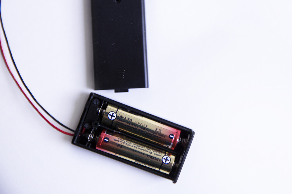
Your kit has a battery pack (and two AA batteries), so that's your power source.
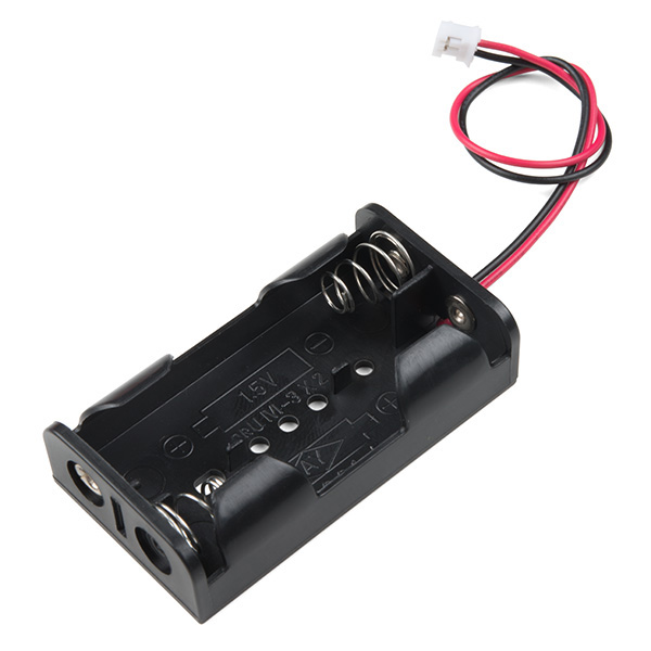
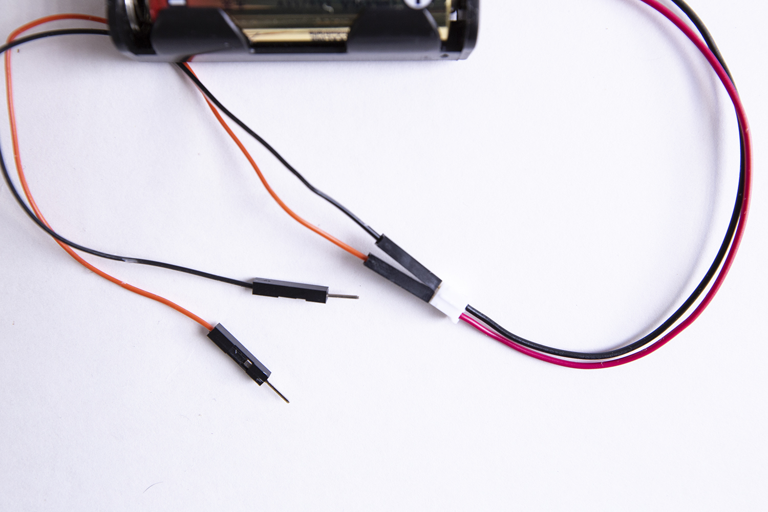
The battery pack has a JST connector (the small, white, rectangular box at the end of the red and black wires), which makes it easy to use with many types of electronics, like micro:bits or Gemmas. But we won't be using the JST connector, so we're going to attach jumper wires -- short lengths of wire that can be used to connect components.
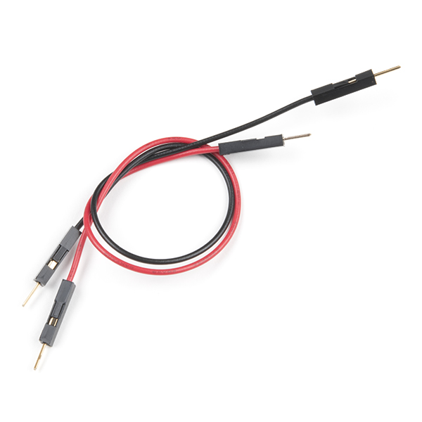
You can either make your own jumper wires by stripping the ends of short lengths of wire, or you can use ready-made jumper wires that have connector pins on the ends ends, like the ones in your kit.
Take one red and one black jumper wire and insert them into the JST connector, like this:
But there is a convention (or normal way of doing things) in electronics where red is used for positive (+) and black for negative (-), so when you look at your battery pack -- or any other component you buy that comes with wires already attached -- you can easily tell positive from negative.
I usually try to make things as easy for myself as possible, and using the same red (+) /black (-) convention as the electronics manufacturers makes it easier for me to trace my circuits -- and for other people to troubleshoot them too!
Insert your AA batteries -- make sure they're pointing in the right directions -- and, voilà! your voltage source is ready to go.
2. The Load
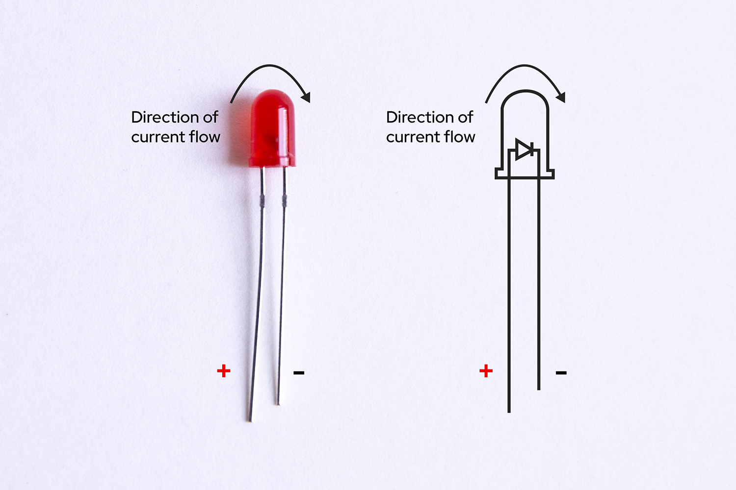
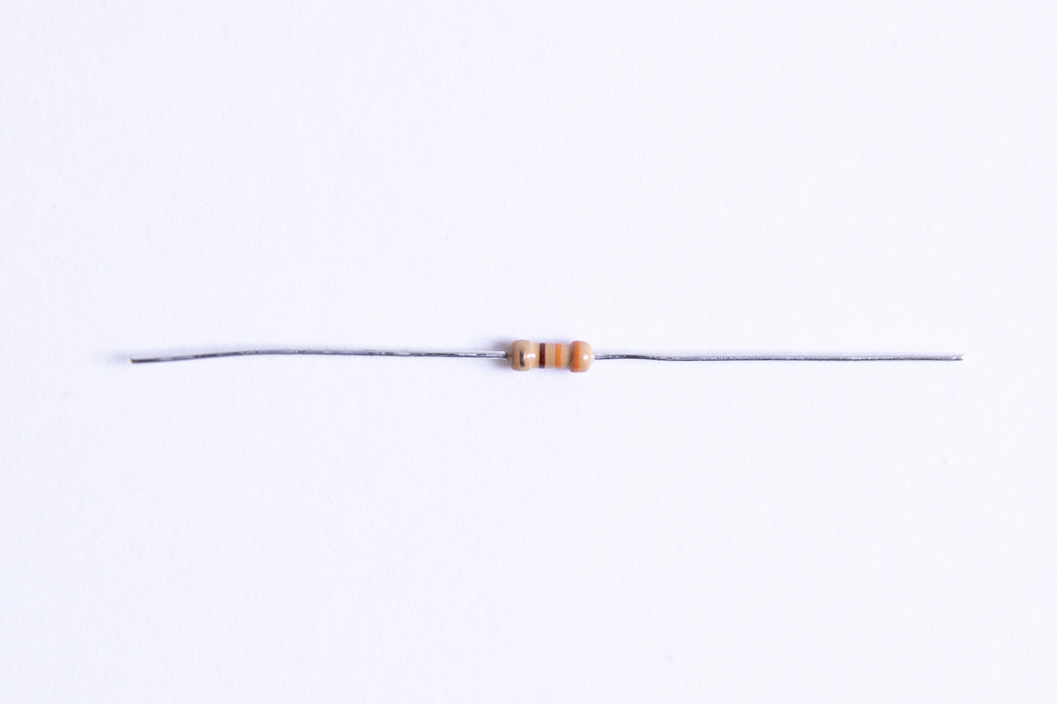
We'll use an LED, or Light-Emitting Diode, as the load for this circuit. If you look at one of the LEDs that came with your kit, you'll see that it has two wire legs, a longer one and a shorter one, both attached to the red "bulb."
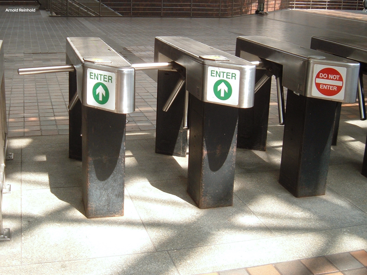
LEDs are polarized which means they can only be connected to a circuit in one direction (if you want them to work, that is!). They're also called directional components, and you can think of them like the turnstile that you might go through at an airport or bus station -- it only turns in one direction.
In an LED the longer leg is the positive (+) connection (or anode) and the shorter leg is the negative (-) connection (or cathode). Current must enter the LED via the cathode (+) and exit via the anode (-) -- the turnstile only works in that direction.
My way of remembering which leg is positive is to think about the fact that drawing a plus symbol (+) takes twice as much "line" to draw as a minus symbol (-), so the (+) leg has to be longer than the (-) one.
3. The Circuit Path
This is where we hit a bit of a problem. The LED has wires sticking out of it, but unless you have extra hands helping you out, it's kind of hard to connect all these parts together -- remember, there can't be any gaps, as a circuit has to be a closed path.
You could solder these components together (and probably would if you expected this to be a permanent installation), but soldering -- especially soldering small parts -- requires some skill and practice. You could also try to twist the jumper wires together with the LED legs ...but that's not as easy as it sounds, and if you want to change it later, your wires are all bent up and likely to break.
And that's where the breadboard comes in really handy. A breadboard is designed to let you make new circuits quickly -- and to change them just as quickly -- all without damaging any of your components. For this reason it's perfect for prototyping -- building an initial version of something so that you can test it and refine it later.
What makes a breadboard so special?
Even though it looks like a plain piece of plastic with holes in it, a breadboard has hidden connections inside it that allow you to create circuits without soldering or twisting together wires. Pretty cool!
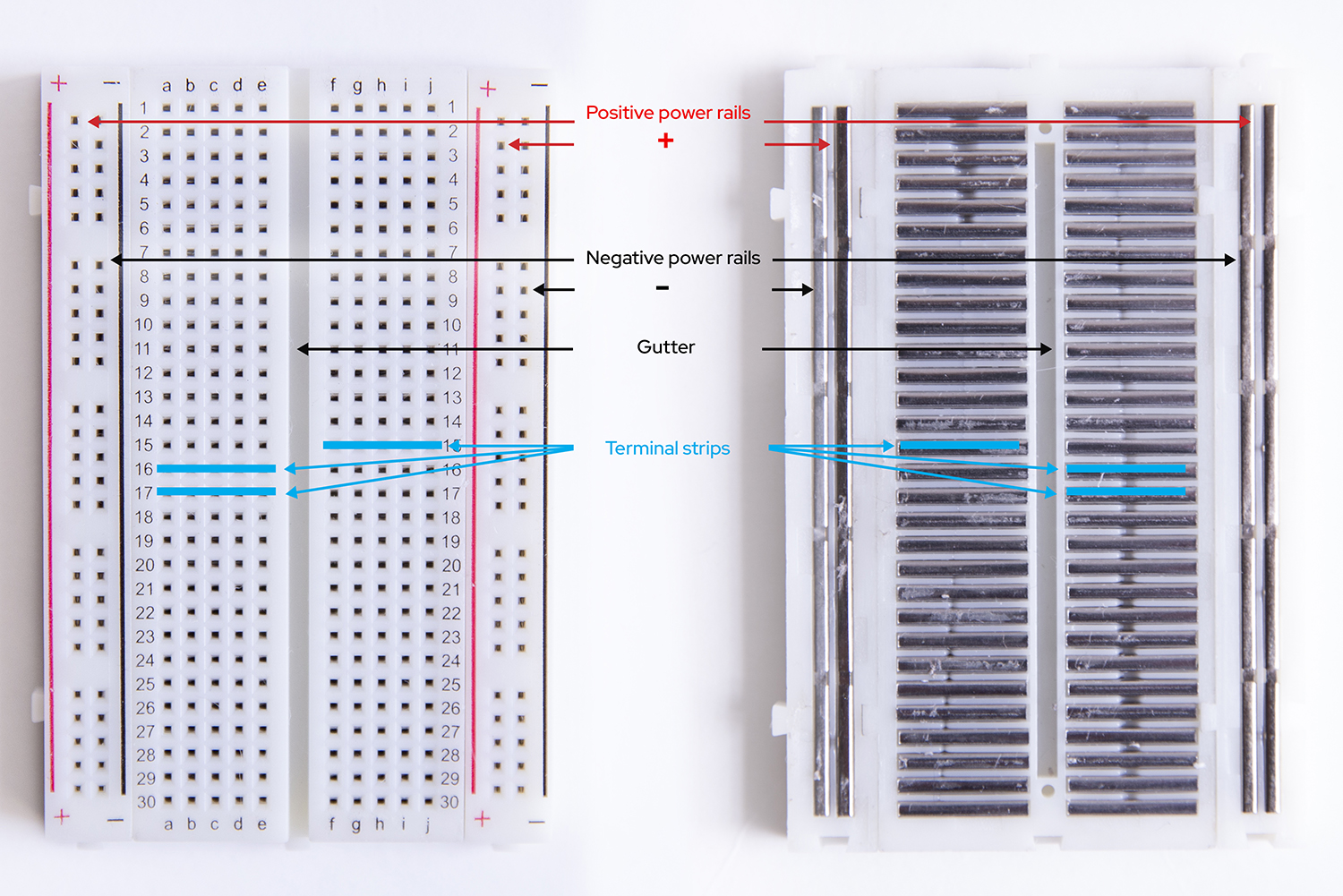
Take a look at the breadboard included in your kit:
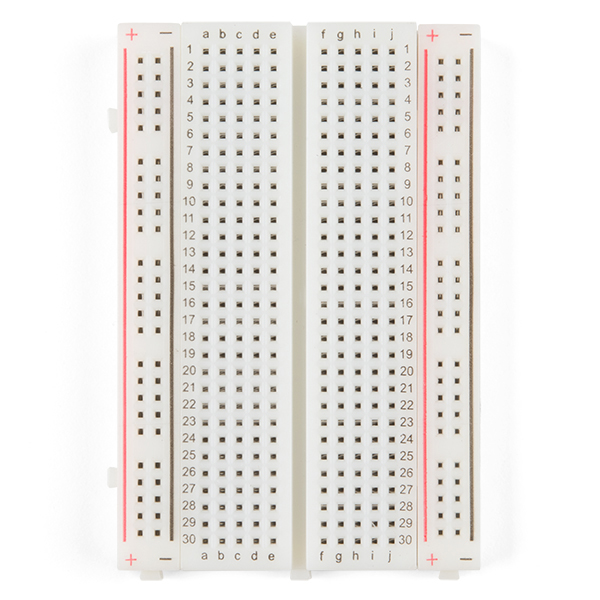
First, notice that there are two long columns of holes running down each side of the board, one with a red line beside it, and one with a black line. Those are called the power rails (or power buses) and all of the holes in a single power rail are connected to each other. Therefore, if something is connected to one hole in the column, it's connected to all the other holes in the column.
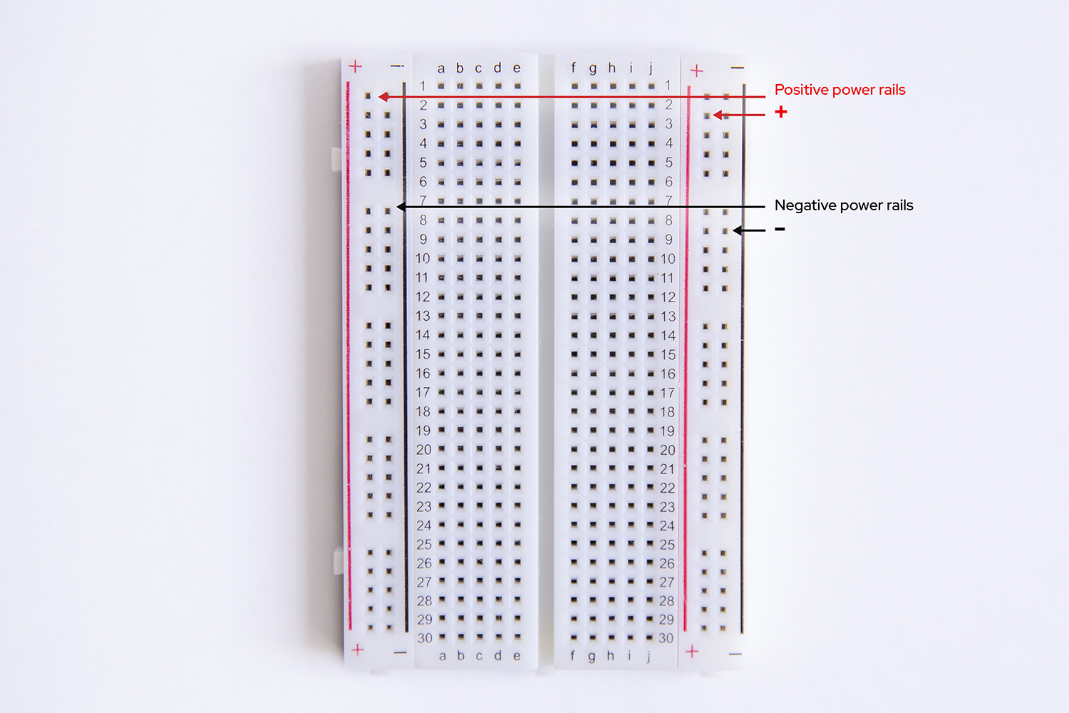
Generally, when you're working on a circuit, you'll connect the positive end of a power source (or cathode), like the positive lead from your battery pack, to the (+) power rail, and then you connect your next component to any of the other holes in that same (+) power rail to give it power. Convenient!
The (+) and (-) markings are there to help you keep things straight, but are actually arbitrary -- you could connect the positive lead from your battery pack to the (-) power rail and then connect your next component to another hole in the (-) power rail and things would still function perfectly (but why would you -- that's confusing!).
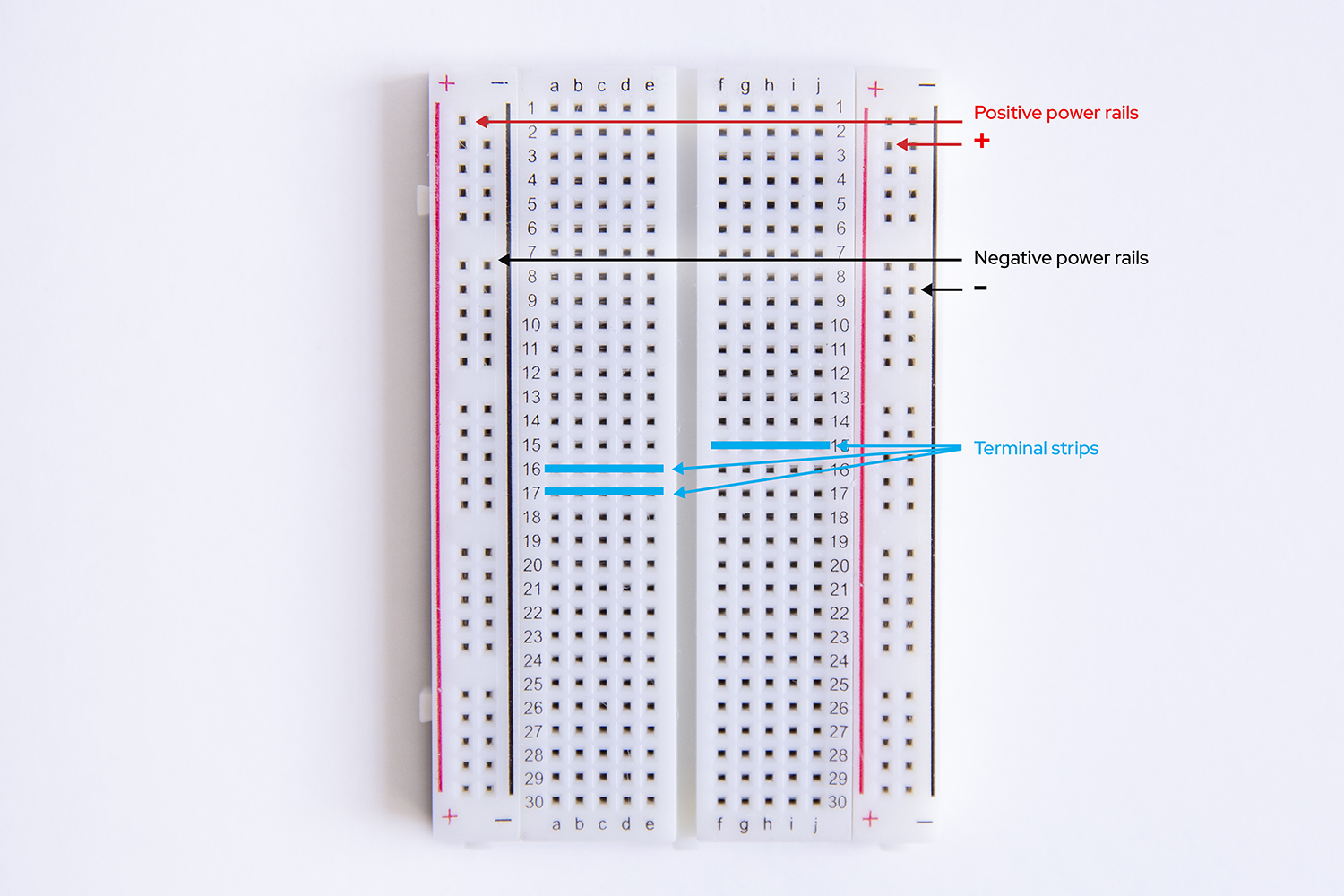
Second, all the holes in the same numbered row (called a "terminal strip") are connected to each other -- as long as you stay on one side or the other of the "gutter" or ravine that runs down the middle.
By the way, the "gutter" is there so that Dual Inline Processor Chips (DIP Chips!) can straddle the gap, allowing the two legs opposite each other to connect to different components (if there weren't a gap, the legs would be on the same terminal strip...and would be connected).
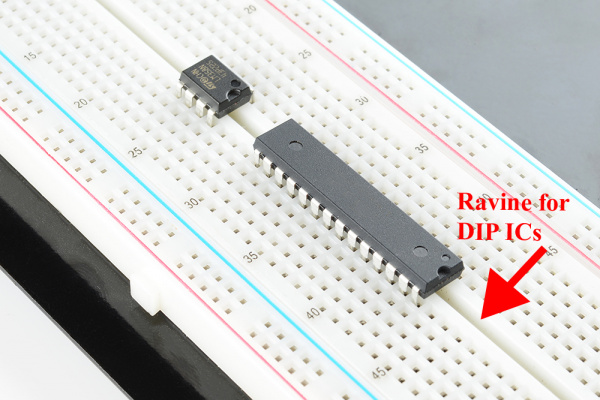
That ravine is sort of "no man's land" for connections, though: unless you deliberately cross it (which you can do with any component -- more on that in a minute), the terminal strips on either side of the gap are not connected to each other.
So, a through e are connected to each other, and f through j are connected, but a-e aren't connected to f-j.
Below you can see the parts labeled on the outside of the breadboard as well as the "guts" of the breadboard -- the metal connections inside the breadboard that make it work.
Why is this useful?
Now, instead of trying to hook up your battery to your light (and whatever other components you're using) by soldering or twisting wires together, you can create your circuit by using the hidden connections in the breadboard. (Want a deeper dive on using breadboards?)
With all that in mind, let's try a couple of configurations for this circuit (and good news -- the breadboard means we can try as many as we want!).
Light it up!
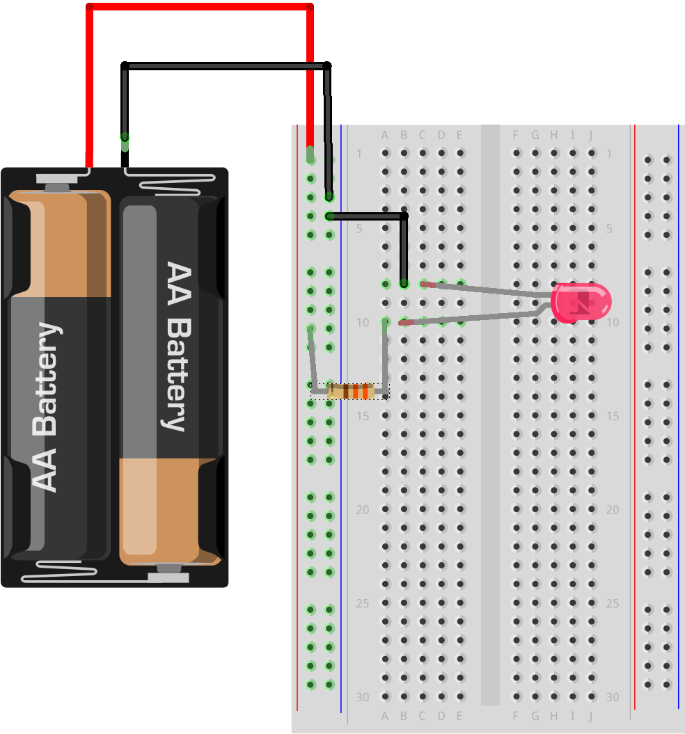
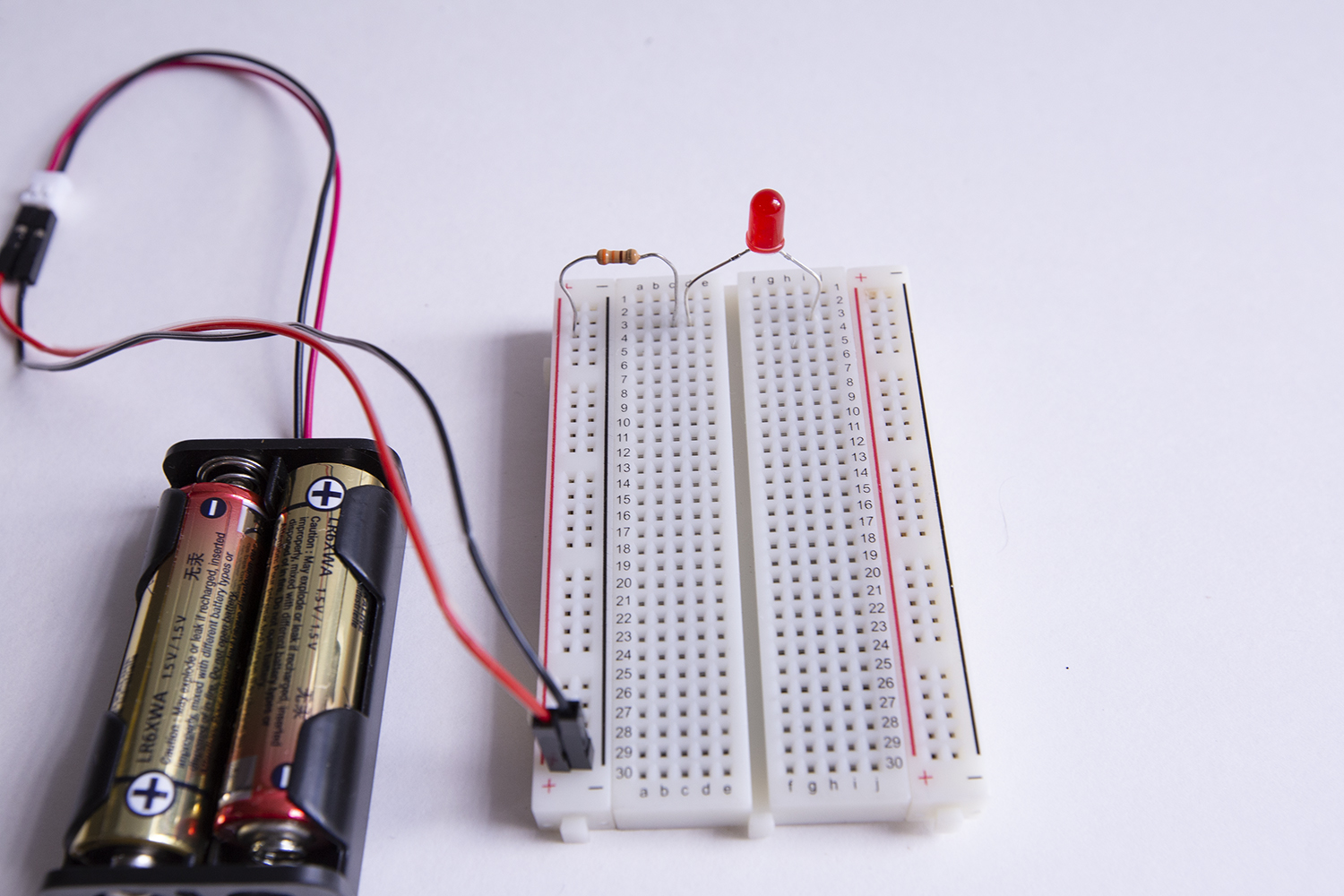
Create your circuit as follows:

- Connect the jumper wire attached to the positive part of the JST terminal to the positive power rail
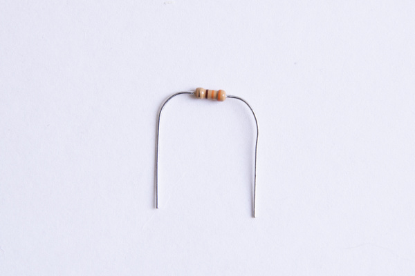
- Connect one end of a 330 Ω resistor to the positive power rail (note: it helps if you bend the resistor into a "u-shape," like this:
- Connect the other end of the resistor to a hole in any "terminal strip." In the picture above, we're using 10A but you can use any hole in any terminal strip you like.
- Connect the positive (longer) leg of the LED to any other hole in the same terminal strip (Note: it doesn't matter whether it goes to the left or the right of the resistor, as long as it's in the same terminal strip, on the same side of the ravine. Here we're using 10B)
- Connect the negative leg of the LED either directly to the negative power rail (if it reaches) or to a hole in a nearby terminal strip and use a jumper wire to connect any other hole in that same terminal strip to the negative power rail.
- Finally, connect the jumper wire attached to the negative part of the JST terminal to the negative power rail.
Rejoice! (And if your LED doesn't light up, don't panic - check out the Troubleshooting section to figure out what's wrong.)
To review, here are the parts of a circuit -- and you now have them all!
☑ a voltage source: the battery pack
☑ a load: the LED
☑ the circuit path: created by using jumper wires and a breadboard
A Few More Things to Try Out
Because breadboards make it easy to try new things out -- or prototype -- there are a couple more fun mini-experiments you can try before moving on to building your "Water-Me Sensor":
Testing Polarity
Remember earlier when we mentioned that current can only flow through a polarized component in one direction (and we asserted that an LED is polarized)?
Reverse the LED
To test that out, try reversing the orientation of the LED in your circuit: pull the LED out and put the negative leg (or cathode) where the positive one (or anode) was and vice versa, and see what happens...

Big ole' nothin', right? No light.
(Ok, put it back the right way, with the positive leg, or cathode connected to the positive power rail via the resistor.)
Reverse the Resistor
What happens if you do the same thing with the resistor, reversing its direction in the circuit?
Everything still works fine, right?
That's because a resistor is a symmetric component -- unlike a polarized component, it can be connected in any direction and still function.
The difference between symmetric and polarized components will become important in Experiment 2, where you build your "Water-Me Sensor".
Bridging the gap
So far we've been working on one side of the ravine, but it might be convenient to have a little more room to spread things out if you were working with a lot of components (or even just a few larger ones).
What could you do if you wanted to (for instance) use the power rails on one side of the gap, but also use the holes on the other side of the gap?
You can use any component to bridge the gap: a resistor, an LED, or a jumper wire.
To test it out, try using your LED to bridge the gap -- you'll have the positive (+) power rail, the resistor, and the positive (+) leg of your LED on one side of the gap, and the negative leg on the other side of the gap. You don't even have to stay on the same row of terminal strips:
You will need to connect to the same set of power rails you started with to complete your circuit, but because the negative leg of the LED is now pretty far away you'll probably need to use a jumper wire (connected to any of the holes in the same terminal strip as the negative leg of the LED) to get back to the negative power rail.
You've bridged the gap and your circuit still works -- now you've got more room on the board to spread things out if you want.
You can skip the section below if you're ready to start creating your "Water-Me Sensor."
A small detour to introduce the concept of Resistance
Current flows more easily through some materials than others. We use the term "resistance" to describe the difficulty that current has flowing through a material, and we measure it in Ohms, or Ω.
The resistor you used in building your circuits above is designed to add "load" to a circuit (without doing anything else). This is useful when the voltage you are working with is too big for one or more of the other components in your circuit.
As an analogy: Think of what would happen if you attached a fire hose to a hydrant at one end, and then tried to attach a garden sprinkler at the other end. Even if you could attach the fire hose to the sprinkler, it's pretty likely that within a few seconds the pressure of the water from the firehose would blow the sprinkler apart.
In this situation, a "resistor" would be installed between the fire hose and the sprinkler and would bleed off the extra water pressure, turning it into something harmless (in the case of electrical resistors, they turn excess current into heat).
Experiment 2: Building Your "Water Me" Signal
Now that you've figured out how a breadboard works, experimented with some basic circuits, and seen first hand how polarity acts as a "gate" for current, it's time to put all that knowledge to work and build your "Water-Me Signal."
Here's a complete walkthrough of Experiment 2, but we've also broken it down step-by-step below.
Building your circuit
Remove the resistor from your last circuit from Experiment 1. We won't need it for the "Water-Me Sensor" because we're adding another component, the sensor, with enough resistance that the LED will be fine. (But keep it -- you can never tell when an extra resistor will be useful).
Remove the LED also, but keep it handy, as you will be needing it. You can leave your battery where it is.
Now take a look at the sensor itself, and you will see three connections:
- VCC, which stands for Voltage Common Collector: this is where current enters the sensor.
- GND, or Ground: the zero voltage point of a circuit, which for a Direct Current (DC) circuit (like this one) is usually connected to the negative terminal (or anode) of the battery.
- SIG, or Signal: the SIG pin on most components means "signal". In this case SIG is an output pin that varies the amount of current sent in response to changes in conductivity between the sensor prongs. That's a lot of info, but for now, think of SIG as the "information out" line for the sensor.
Top side of sensor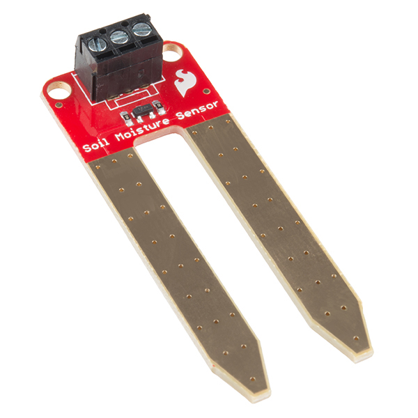 |
Bottom side of sensor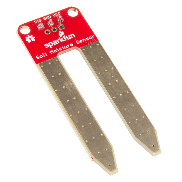 |
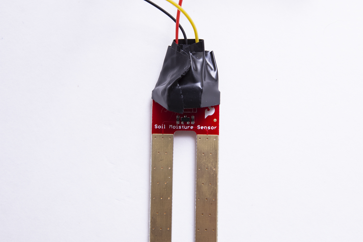
To get the sensor ready to use in your circuit, insert one end of a red jumper wire (we recommend red, but you do you -- remember, they're all the same on the inside) into the hole marked VCC and use the small screwdriver included with the kit to tighten the set screw, capturing the wire. (It doesn't have to be super-tight, just enough that it doesn't pull out easily.)
Now do the same thing two more times, putting a black jumper wire into the GND pin and a jumper wire of whatever color you want into SIG.
Your sensor should look like this when you're finished:
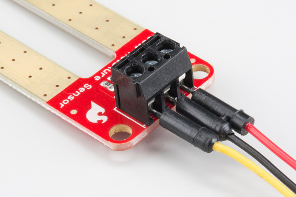
For example, I always use yellow for "SIG" -- it makes it easier to spot those "signal wires" when I'm looking at a complex circuit.
Next, insert the other end of the VCC jumper wire (which is red, if you are using the conventional color scheme) into the positive (+) power rail.
Insert the other end of the jumper wire attached to the SIG pin into any hole in any terminal strip -- your choice! Then insert the negative leg (-) of the LED so that it is also connected to the SIG jumper wire, which is yellow if you're using my color suggestions (Hint: any hole in the same terminal strip will work).
Insert the positive leg of the LED into the (+) power rail -- directly if it's close enough, or use a jumper wire in between if it's not.
Finally, insert the other end of the sensor GND jumper wire (probably black) into the negative (-) power rail.

Your "Water-Me Sensor" should be lit up (because it's dry!).
Project checklist
☑ Read Requirements and Assemble Tools
☑ Read the Instructions
☑ Identify the Parts
☑ Build Your Project
☐ Testing
☐ Show it off!
Testing
To test your "Water-Me Sensor" you can use a paper towel in place of the hydroponic felt that will be in the planter. Touch both tips of the sensor prong to the paper towel -- your LED should stay lit.
Now, take a little water and pour it onto the paper towel, then touch the prong tips to it (make sure both prong tips are touching the wet part of the towel).
Hopefully, your LED just went out (if not, check the Troubleshooting section).
Project checklist
☑ Read Requirements and Assemble Tools
☑ Read the Instructions
☑ Identify the Parts
☑ Build Your Project
☑ Testing
☐ Show it off!
That's pretty cool, but...
How does it work?
What's going on with the sensor? How does it "know" when there's no moisture?
The paper towel, when dry, is a poor conductor of electricity (most fabrics are).
But most water is a good conductor of electricity, so adding moisture increases the conductivity between the prongs, meaning more current can flow between them.
That's important because this sensor detects the amount of conductivity between the prongs and, based on that, changes the amount of current that gets sent to GND or SIG. The more conductivity there is (the more electricity can flow between the two prongs) the more current is sent to SIG (and the less gets sent to GND).
This means that when your felt is moist -- and is therefore a better conductor of electricity -- there's more current going to SIG and less to GND.
But finding perfectly pure water is almost impossible -- and definitely not something you should try in an experiment with electricity!
Reversing the circuit to see what happens
This next part is easier to understand if you see it for yourself, so let's take apart the perfectly good circuit you just finished. (I know, it sounds ridiculous, but trust me it's worth it...and we'll put it back afterwards.)
In the circuit that you built, reverse the way the LED is connected, so that the positive (+) leg (the longer one) is connected to the SIG pin and the negative (-) leg (the shorter one) is connected to ground, using jumper wires as necessary:
More conductivity between the sensor prongs causes current to get shifted to the SIG pin, so you might expect that when moisture increases the LED would light up... and, in fact, if you take the prongs of your sensor and barely touch them both to your paper-towel-with-a-puddle-on-it, that's exactly what happens.
(You've now built a moisture sensor -- people buy these to put in their basements or crawlspaces to sense water leaks! Nifty, huh?)
Back to the "Water-Me Sensor"
Before we go any further, go ahead and switch that LED back the way it was before: with the negative (-) leg of the LED connected to the SIG pin and the positive (+) leg connected to the positive (+) power rail.
To test that you've reconfigured it correctly, make sure the sensor isn't touching the wet paper towel (and that there's nothing else -- like your finger -- causing a connection between the two prongs). Your LED should be lit up (if not, see Troubleshooting).
But how does switching the "direction" of the LED turn a moisture sensor into a "Water-Me Signal" (or, to think of it another way, an "anti-moisture signal")?
In this configuration, voltage comes in via the positive power rail and goes through the LED. Remember, though, that a circuit has to be complete to work, so where is the rest of the circuit path -- where does it connect back to ground?
When there is conductivity between the prongs of the sensor, all the current goes out the SIG pin, which means there's no connection between the sensor and the GND pin. With no connection to GND, the circuit isn't complete, so the LED can't light.
But when there is no conductivity, the sensor opens the connection to GND, which means that there is now a complete circuit: the positive power rail is connected to the LED and the moisture sensor, and the moisture sensor is connected to GND.
Experiment 3: Planting Your Farm
Prep Your Sensor
You may want to wrap the connections on your sensor with electrical tape to help protect the connections. It's not absolutely necessary -- and if you keep the connections out of the actual wetness (and don't pour water on them!) -- you should be fine even if you don't, but a little extra insurance never hurts.
Prep Your Container and Hydroponic Felt
If you're using a recycled container make sure it's washed out well before starting.
Instead of soil, we're using hydroponic felt, which works as an alternative to using soil for microgreens because its structure is ideal for young plant roots to thrive. The felt fibers hold in water so that plant roots can absorb it and grow.
It comes in a 4"x4" sheet, so you might need to trim it to fit the bottom of your container. (You have two sheets -- one is a spare -- so you only need to trim one right now.)
If you do need to trim your felt, use your pencil to trace the bottom of your container's outline lightly on your felt, then use your scissors to trim your felt a just a little inside the line you drew, so it will fit nicely on the bottom.
If you do have to trim your felt, save the scraps. If your location is very warm, you live in a place with less humidity, or you have a very sunny spot for your planter, you may find out that your felt dries out in less than 24 hours. If that's the case, you can wet those leftover bits and place them on top of your seeds so that more moisture is maintained.
Plant Your Seeds
We're planting microgreens, which are like baby herbs or veggies. Read more about microgreens and how to plant and take care of them.
Take your felt and soak it in water, then wring out any extra moisture. The felt should be wet, but water shouldn’t drip out if you hold it by one edge.
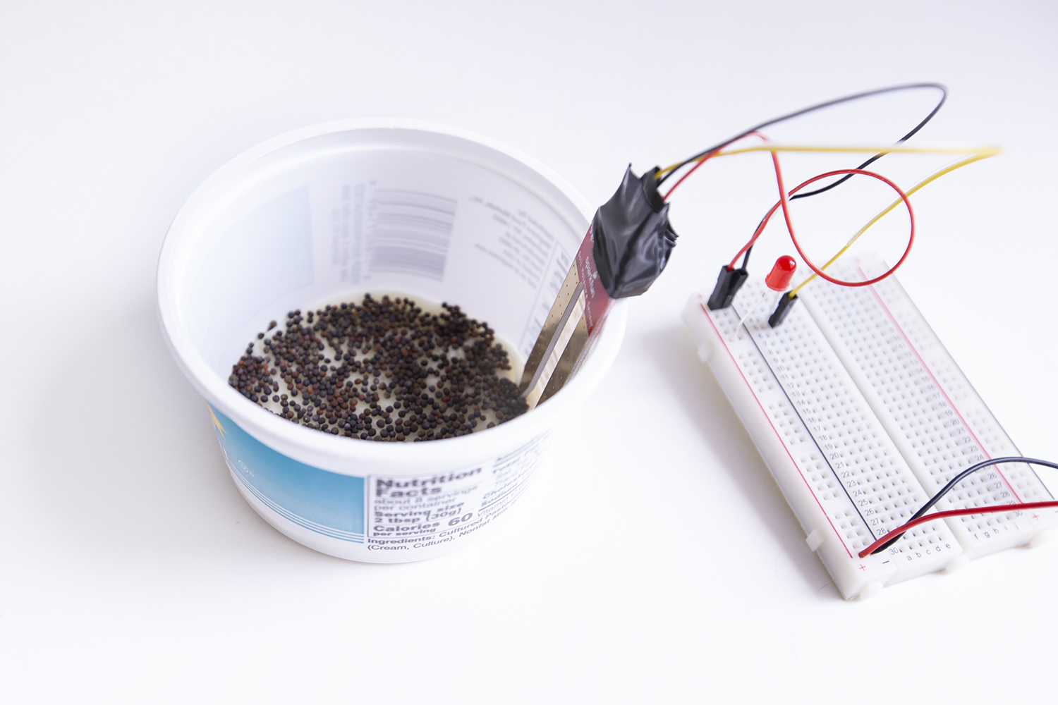
Place the wet hydroponic felt in your planter, and sprinkle microgreen seeds to cover the bottom of the planter.
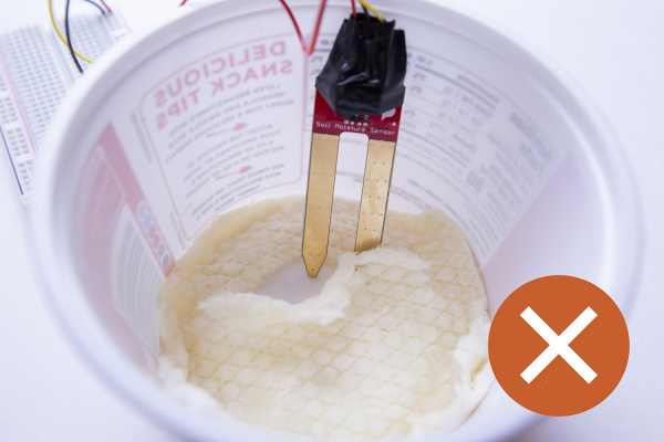
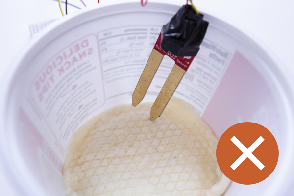
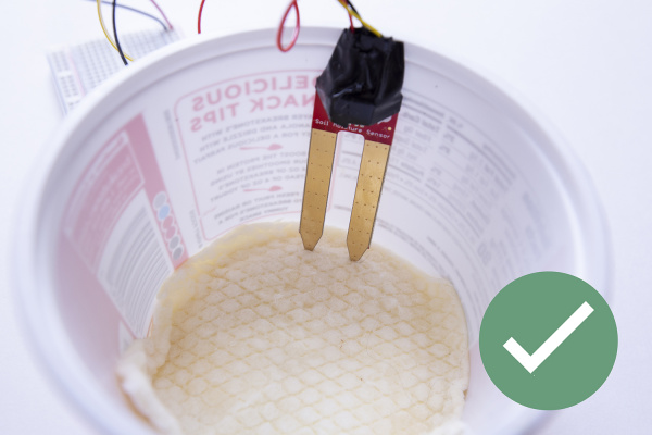
Put your "Water-Me Sensor" near enough to your planter that both tips of the sensor prongs can reach inside and touch the felt. You may need to make a little platform for your sensor to sit on if your planter is so deep that the sensor prongs can't reach without stressing the jumper wire connections.
Place the sensor so that both prongs are just a little bit dug into the felt. You don't want them so far in that they are touching the bottom of the container, but you do want them "in" the felt rather than just sitting on top.
Tend Your Farm
Place your whole farm setup near a window with sunlight and check your soil moisture sensor to make sure that your plants have enough water!
The "Water-Me Signal" is your friend here -- check it every day. It's easy to overwater the seeds, and if you do, they will mold (ick!), so don't overdo it. You want damp, not soggy or waterlogged.
Enjoy watching your microgreens grow! Your second piece of felt can be used to try a different variety of seed or a different growing environment. What happens if you plant the same seeds in a warmer environment, for instance? Do you have to water them more often? Do they grow as tall?
Project checklist
☑ Read Requirements and Assemble Tools
☑ Read the Instructions
☑ Identify the Parts
☑ Build Your Project
☑ Testing
☑ Show it off!
Troubleshooting
Here's some things to look for if your project isn't working (and for some great illustrations and further explanations of these, see "Common Mistakes when Using a Breadboard" on the Science Buddies site.)
| If your LED won't light: | |
| 1. Check your connections | Common sources of connection errors
|
| 2. Check your power |
|
| If your plants aren't growing: | Check for mold. | If your seeds are fuzzy and your felt is white or green, you may have added too much water.
Remember: the seeds don't need much water; the felt helps to retain moisture; and that's why you built a "Water-Me Sensor", right? If you add too much water, your seeds may mold. If this happens, your best bet is to use your spare piece of felt and start over with some new seeds -- and less water! :-) |
| See if your felt is completely dry. |
|
| Are they getting enough light? | Plants need light to grow. Check the information that came with your seeds to see how much light they need. |
Resources and Going Further
More information that may help you along in learning more about the world of electronics.
More in-depth exploration of concepts and parts in this kit
- Circuits: the basics of how circuits work, as well as links to more in-depth information
- Polarity: when direction matters
- How voltage dividers work - Learn more about the voltage divider the water sensor uses to shift the voltage from GND to SIG.
- Resistors: what are they, and why do you need them?
- Light-Emitting Diodes (LEDs): everything you ever wanted to know about how these tiny lights work
- Breadboards: a deeper dive into the interior mechanics of the breadboard
- Information on microgreens: what they are, how they are different from sprouts, and more
More open source farm projects
- DIY Arduino Garden Projects: Learn how to build a self-watering system so you don’t need to water plants every time your soil moisture sensor lights up
- The Thirsty Flamingo Project - an Instructables project that uses the same sensor used in this project, a 3D printed flamingo, and an Arduino to level-up the moisture sensor
Full Kit Contents List
Things sometimes break or get lost, it's part of making and tinkering! If you need to replace a part here is a list of the individual components that make up the Red Hat Co. Lab Farm Kit from the SparkFun catalog.
Remember that you'll need to add your own seeds and a container!
Licenses and Copyrights
Below are the open source licenses held by both SparkFun and Red Hat on the content of this experiment guide.
| Author(s) | Gina Likins, with enormous help and troubleshooting from SparkFun |
| License | Co.Lab License Information
Co.Lab uses two different licenses for our files:one for Content, like the Activity itself, and one for Code, whether downloadable or presented as excerpted source code in documentation.ContentCopyright © Red Hat. Except where otherwise indicated, this document and the photos contained in this document are licensed under Creative Commons Attribution-ShareAlike 4.0 International. Modifications of this work may not include the Red Hat or Co.Lab logos, other than as they may appear in photos of Project Artifacts. “Project Artifacts” means the tangible physical artifacts included with the Red Hat Co.Lab Farm Kit, such as postcards, stickers and packaging. License: Co.Lab content is released under Creative Commons Attribution-ShareAlike 4.0 International Note: This is a human-readable summary of (and not a substitute for) the license. A copy of the Creative Commons Attribution-ShareAlike 4.0 International license can be found here: "https://creativecommons.org/licenses/by-sa/4.0/legalcodeYou are free to: Share — copy and redistribute the material in any medium or format. Adapt — remix, transform, and build upon the material for any purpose, even commercially. The licensor cannot revoke these freedoms as long as you follow the license terms. Under the following terms:Attribution — You must give appropriate credit, provide a link to the license, and indicate if changes were made. You may do so in any reasonable manner, but not in any way that suggests the licensor endorses you or your use.ShareAlike — If you remix, transform, or build upon the material, you must distribute your contributions under the same license as the original. No additional restrictions — You may not apply legal terms or technological measures that legally restrict others from doing anything the license permits. Notices:You do not have to comply with the license for elements of the material in the public domain or where your use is permitted by an applicable exception or limitation. No warranties are given. The license may not give you all of the permissions necessary for your intended use. For example, other rights such as publicity, privacy, or moral rights may limit how you use the material.Code Unless otherwise specified, all Code for the Red Hat Co.Lab Farm Kit project is available under the terms of the MIT license. The MIT License (MIT) Copyright © 2020 Red Hat Permission is hereby granted, free of charge, to any person obtaining a copy of this software and associated documentation files (the "Software"), to deal in the Software without restriction, including without limitation the rights to use, copy, modify, merge, publish, distribute, sublicense, and/or sell copies of the Software, and to permit persons to whom the Software is furnished to do so, subject to the following conditions: The above copyright notice and this permission notice shall be included in all copies or substantial portions of the Software. THE SOFTWARE IS PROVIDED "AS IS", WITHOUT WARRANTY OF ANY KIND, EXPRESS OR IMPLIED, INCLUDING BUT NOT LIMITED TO THE WARRANTIES OF MERCHANTABILITY, FITNESS FOR A PARTICULAR PURPOSE AND NONINFRINGEMENT. IN NO EVENT SHALL THE AUTHORS OR COPYRIGHT HOLDERS BE LIABLE FOR ANY CLAIM, DAMAGES OR OTHER LIABILITY, WHETHER IN AN ACTION OF CONTRACT, TORT OR OTHERWISE, ARISING FROM, OUT OF OR IN CONNECTION WITH THE SOFTWARE OR THE USE OR OTHER DEALINGS IN THE SOFTWARE. |