Experiment Guide for the Red Hat Co.Lab Farm Kit
 D___Run___,
  Gina Likins
Experiment 1: Breadboards and Basic Circuits
Here's a walkthrough showing all the steps of Experiment 1, but you can also see each of them broken down separately below.
What is a circuit?
A circuit is a closed loop that electricity can travel around that, at its most basic, consists of three parts:
- a voltage source: the power for the circuit
- a load: the thing that is being powered, like a motor, buzzer or light
- the circuit path: the continuous path that the current follows as it travels around the circuit
An example of a simple circuit would be a power source (like a battery), a load (like a light), and the circuit path (the wires that connect them).
Make a Simple Circuit
1. The Voltage Source
Your kit has a battery pack (and two AA batteries), so that's your power source.
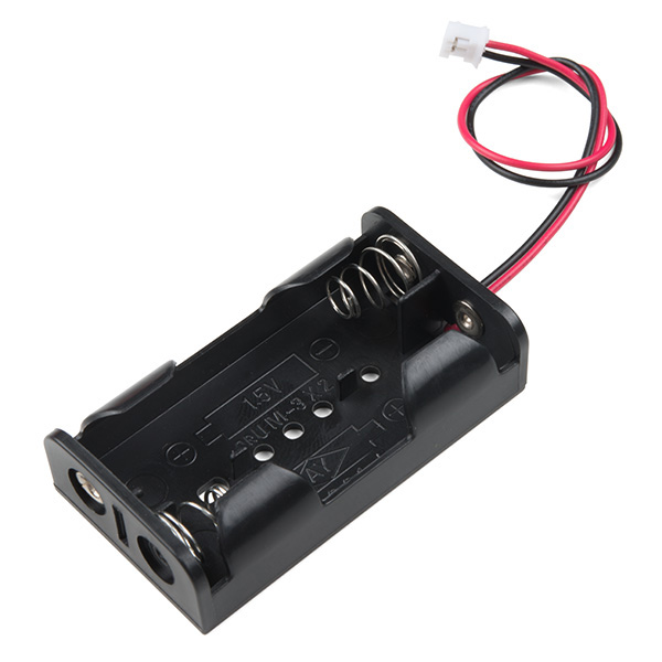
The battery pack has a JST connector (the small, white, rectangular box at the end of the red and black wires), which makes it easy to use with many types of electronics, like micro:bits or Gemmas. But we won't be using the JST connector, so we're going to attach jumper wires -- short lengths of wire that can be used to connect components.
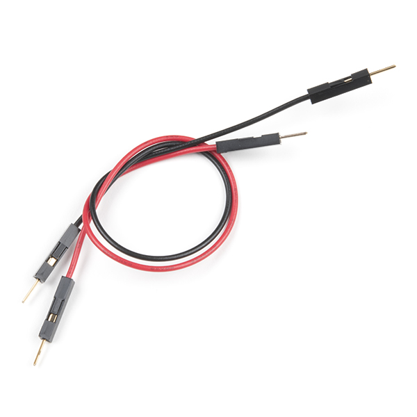
You can either make your own jumper wires by stripping the ends of short lengths of wire, or you can use ready-made jumper wires that have connector pins on the ends ends, like the ones in your kit.
Take one red and one black jumper wire and insert them into the JST connector, like this:
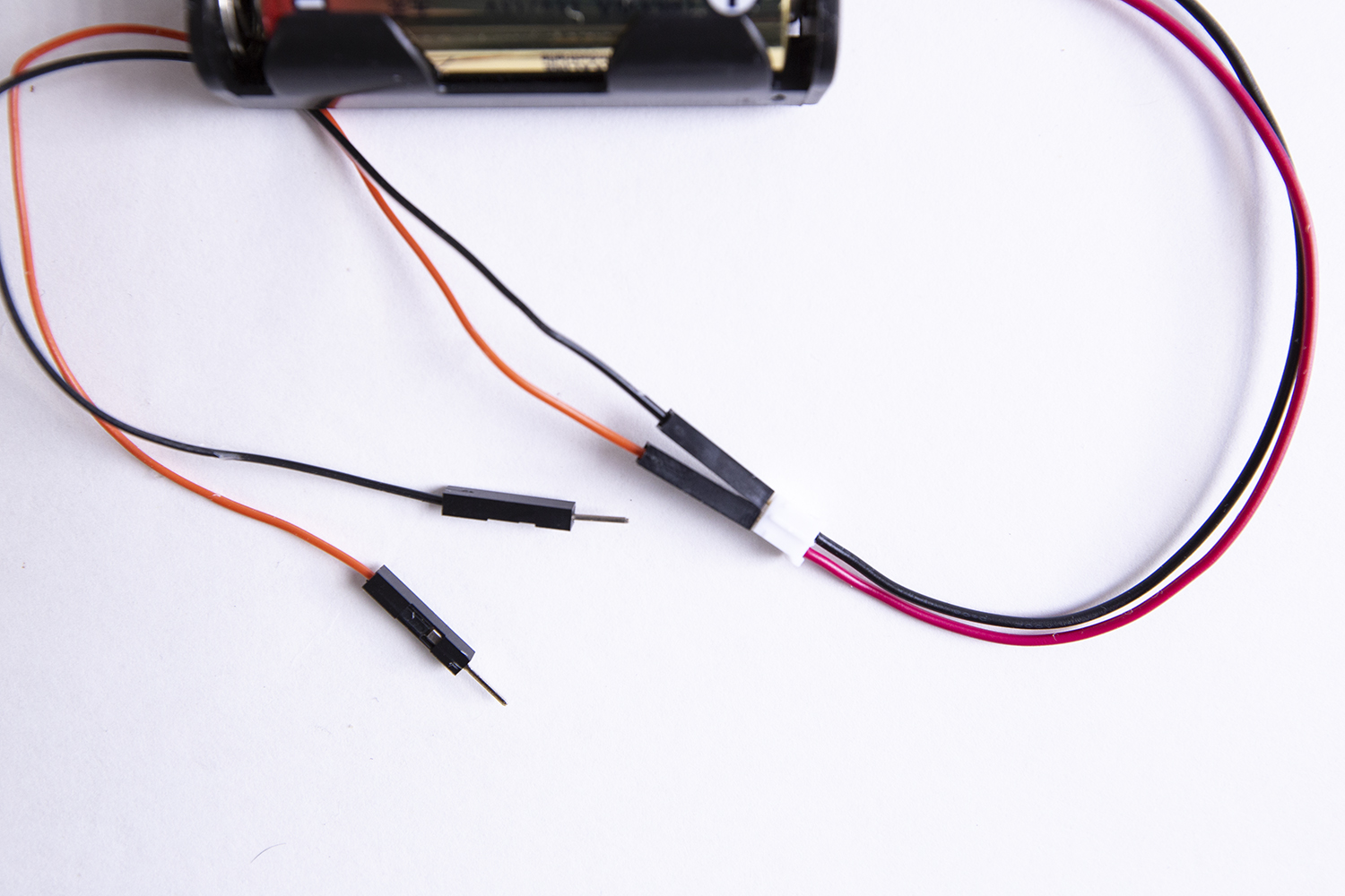
But there is a convention (or normal way of doing things) in electronics where red is used for positive (+) and black for negative (-), so when you look at your battery pack -- or any other component you buy that comes with wires already attached -- you can easily tell positive from negative.
I usually try to make things as easy for myself as possible, and using the same red (+) /black (-) convention as the electronics manufacturers makes it easier for me to trace my circuits -- and for other people to troubleshoot them too!
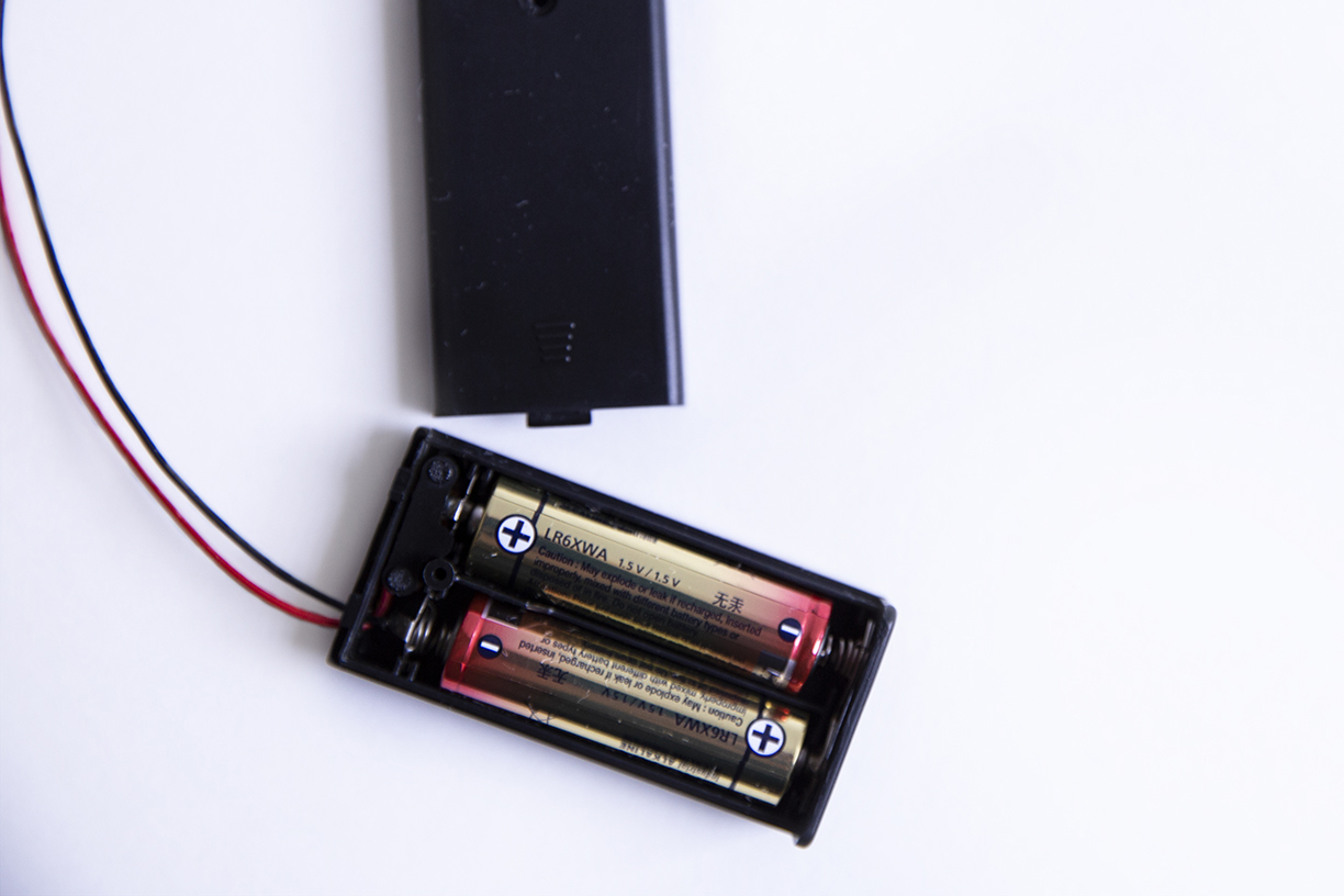
Insert your AA batteries -- make sure they're pointing in the right directions -- and, voilà! your voltage source is ready to go.
2. The Load
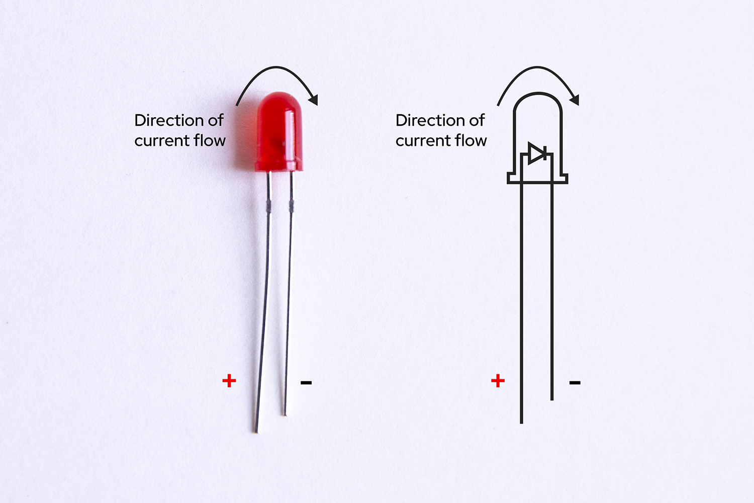
We'll use an LED, or Light-Emitting Diode, as the load for this circuit. If you look at one of the LEDs that came with your kit, you'll see that it has two wire legs, a longer one and a shorter one, both attached to the red "bulb."
LEDs are polarized which means they can only be connected to a circuit in one direction (if you want them to work, that is!). They're also called directional components, and you can think of them like the turnstile that you might go through at an airport or bus station -- it only turns in one direction.
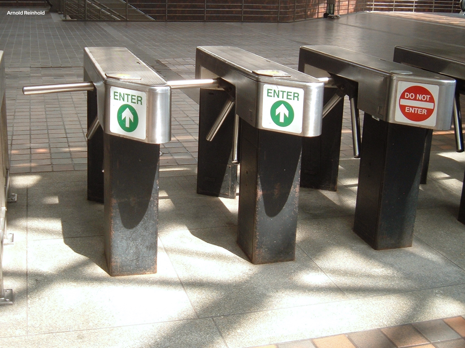
In an LED the longer leg is the positive (+) connection (or anode) and the shorter leg is the negative (-) connection (or cathode). Current must enter the LED via the cathode (+) and exit via the anode (-) -- the turnstile only works in that direction.
My way of remembering which leg is positive is to think about the fact that drawing a plus symbol (+) takes twice as much "line" to draw as a minus symbol (-), so the (+) leg has to be longer than the (-) one.
3. The Circuit Path
This is where we hit a bit of a problem. The LED has wires sticking out of it, but unless you have extra hands helping you out, it's kind of hard to connect all these parts together -- remember, there can't be any gaps, as a circuit has to be a closed path.
You could solder these components together (and probably would if you expected this to be a permanent installation), but soldering -- especially soldering small parts -- requires some skill and practice. You could also try to twist the jumper wires together with the LED legs ...but that's not as easy as it sounds, and if you want to change it later, your wires are all bent up and likely to break.
And that's where the breadboard comes in really handy. A breadboard is designed to let you make new circuits quickly -- and to change them just as quickly -- all without damaging any of your components. For this reason it's perfect for prototyping -- building an initial version of something so that you can test it and refine it later.
What makes a breadboard so special?
Even though it looks like a plain piece of plastic with holes in it, a breadboard has hidden connections inside it that allow you to create circuits without soldering or twisting together wires. Pretty cool!
Take a look at the breadboard included in your kit:
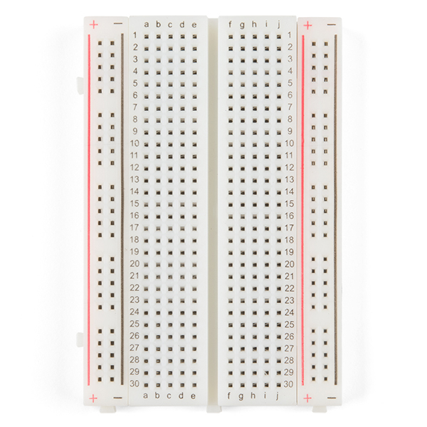
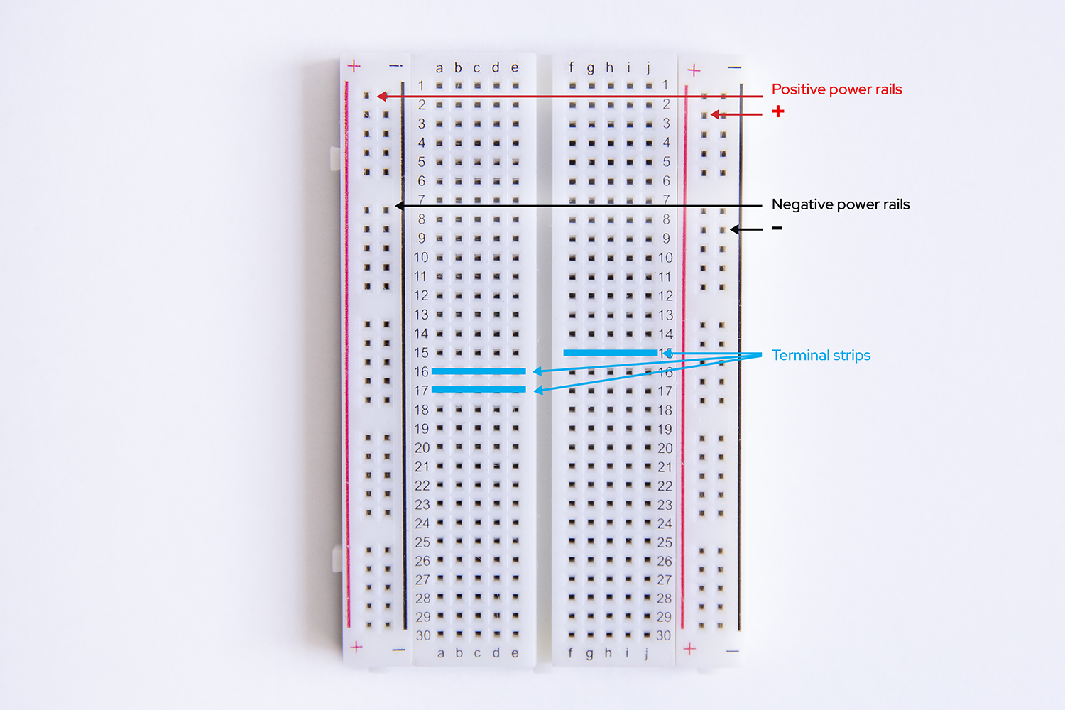
First, notice that there are two long columns of holes running down each side of the board, one with a red line beside it, and one with a black line. Those are called the power rails (or power buses) and all of the holes in a single power rail are connected to each other. Therefore, if something is connected to one hole in the column, it's connected to all the other holes in the column.
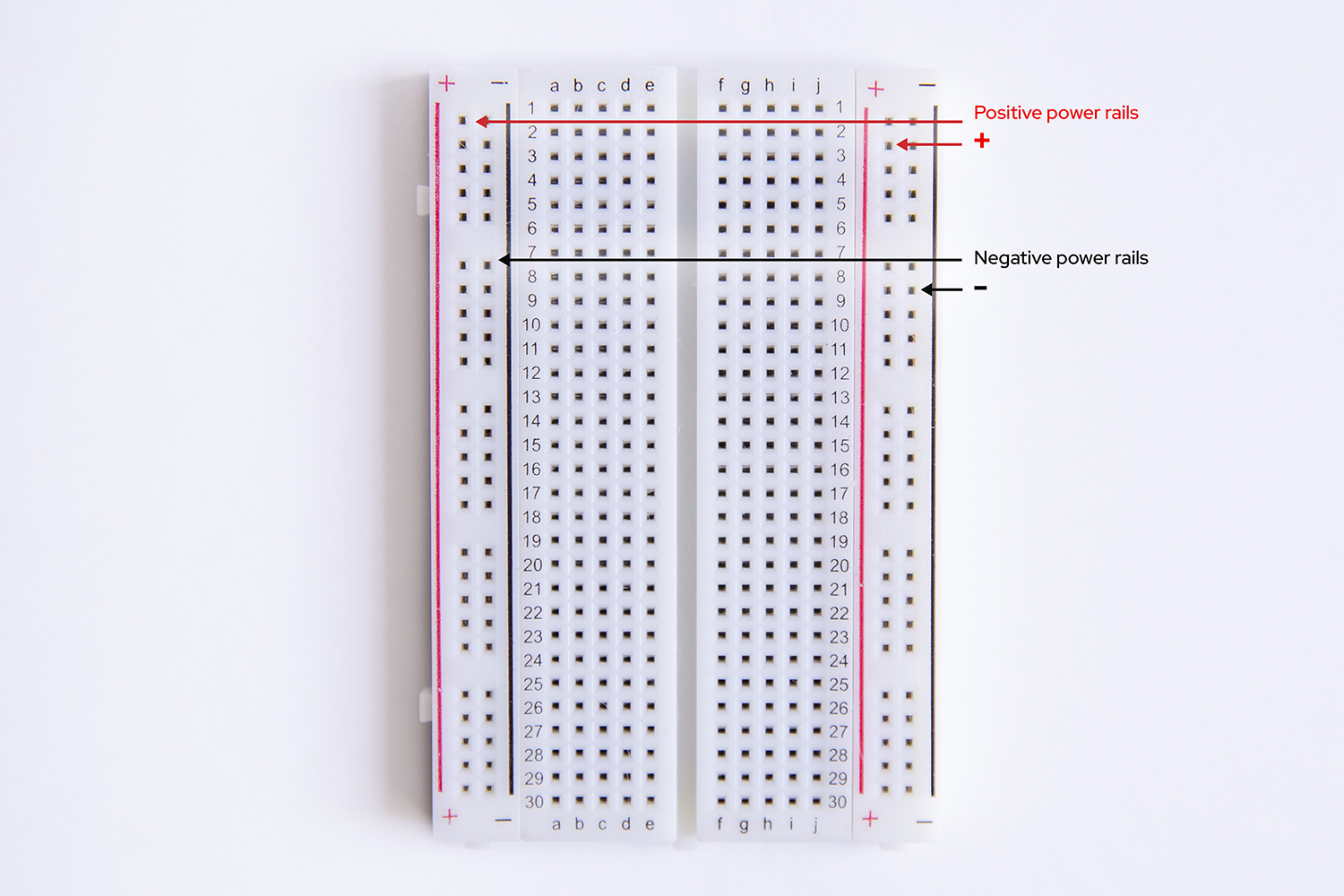
Generally, when you're working on a circuit, you'll connect the positive end of a power source (or cathode), like the positive lead from your battery pack, to the (+) power rail, and then you connect your next component to any of the other holes in that same (+) power rail to give it power. Convenient!
The (+) and (-) markings are there to help you keep things straight, but are actually arbitrary -- you could connect the positive lead from your battery pack to the (-) power rail and then connect your next component to another hole in the (-) power rail and things would still function perfectly (but why would you -- that's confusing!).
Second, all the holes in the same numbered row (called a "terminal strip") are connected to each other -- as long as you stay on one side or the other of the "gutter" or ravine that runs down the middle.
By the way, the "gutter" is there so that Dual Inline Processor Chips (DIP Chips!) can straddle the gap, allowing the two legs opposite each other to connect to different components (if there weren't a gap, the legs would be on the same terminal strip...and would be connected).
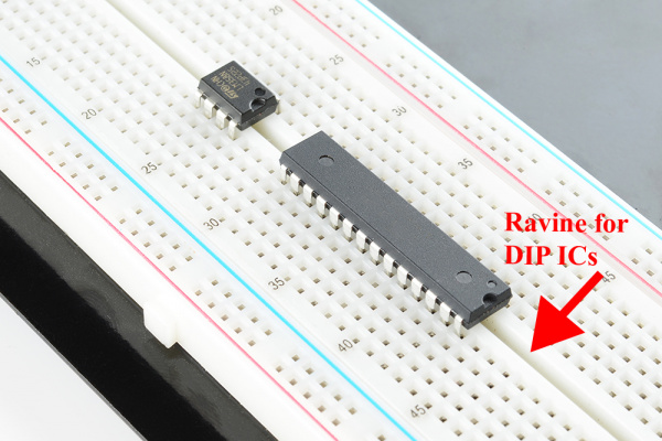
That ravine is sort of "no man's land" for connections, though: unless you deliberately cross it (which you can do with any component -- more on that in a minute), the terminal strips on either side of the gap are not connected to each other.
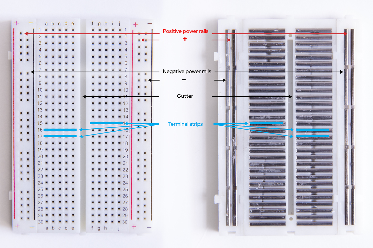
So, a through e are connected to each other, and f through j are connected, but a-e aren't connected to f-j.
Below you can see the parts labeled on the outside of the breadboard as well as the "guts" of the breadboard -- the metal connections inside the breadboard that make it work.
Why is this useful?
Now, instead of trying to hook up your battery to your light (and whatever other components you're using) by soldering or twisting wires together, you can create your circuit by using the hidden connections in the breadboard. (Want a deeper dive on using breadboards?)
With all that in mind, let's try a couple of configurations for this circuit (and good news -- the breadboard means we can try as many as we want!).
Light it up!
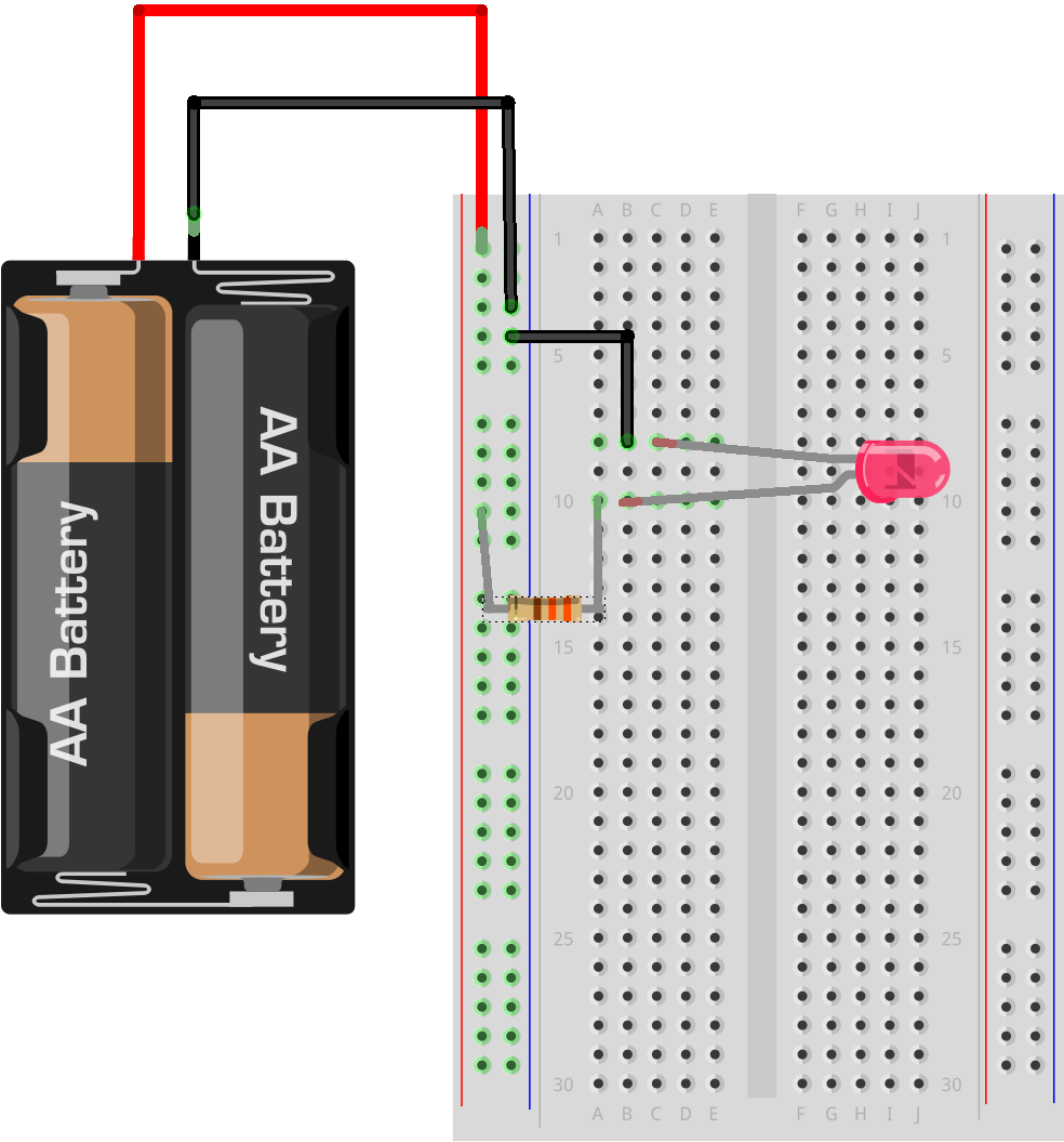
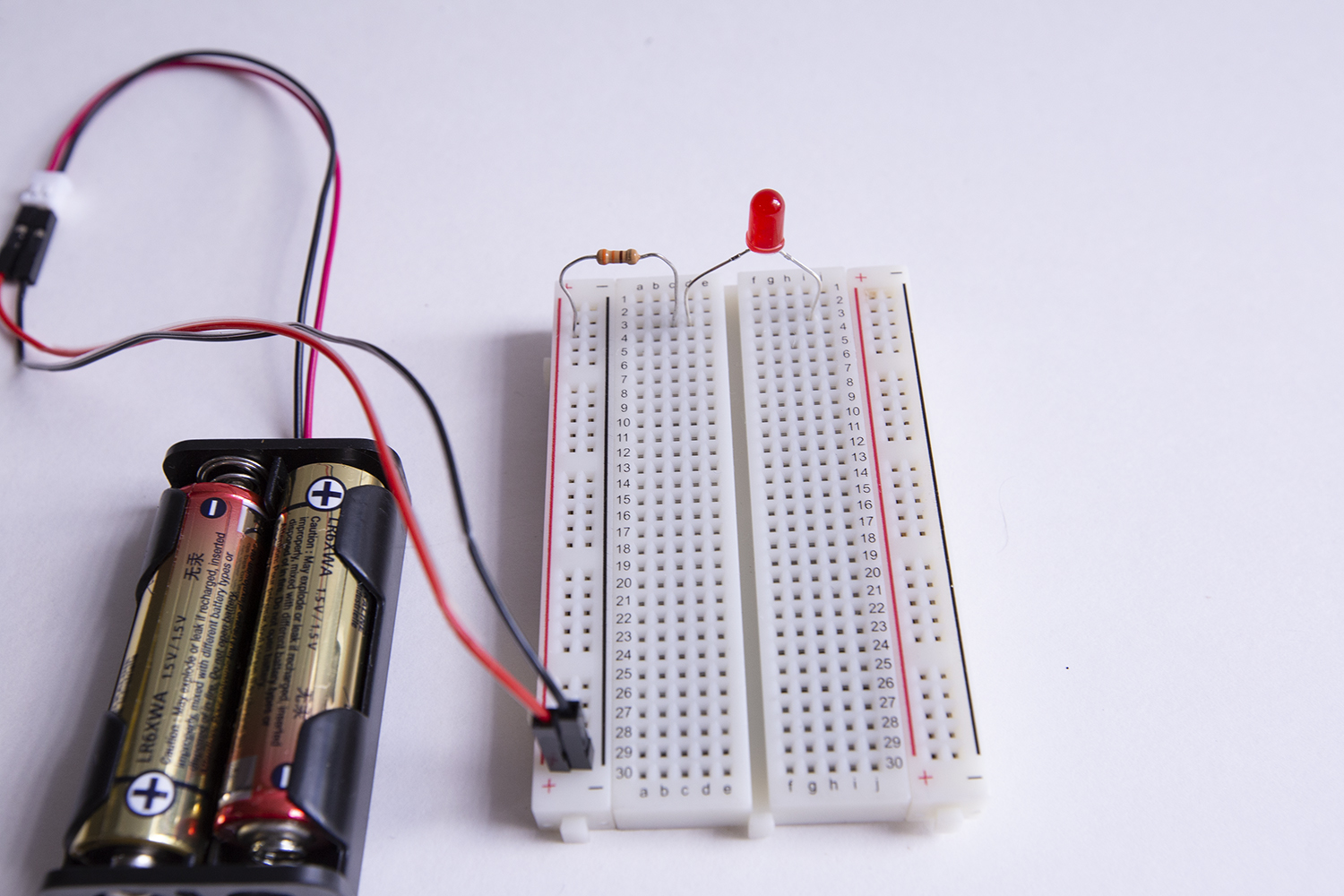
Create your circuit as follows:

- Connect the jumper wire attached to the positive part of the JST terminal to the positive power rail
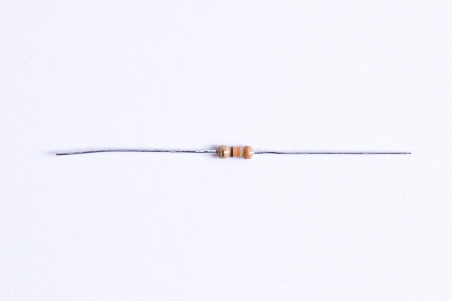
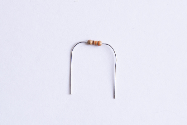
- Connect one end of a 330 Ω resistor to the positive power rail (note: it helps if you bend the resistor into a "u-shape," like this:
- Connect the other end of the resistor to a hole in any "terminal strip." In the picture above, we're using 10A but you can use any hole in any terminal strip you like.
- Connect the positive (longer) leg of the LED to any other hole in the same terminal strip (Note: it doesn't matter whether it goes to the left or the right of the resistor, as long as it's in the same terminal strip, on the same side of the ravine. Here we're using 10B)
- Connect the negative leg of the LED either directly to the negative power rail (if it reaches) or to a hole in a nearby terminal strip and use a jumper wire to connect any other hole in that same terminal strip to the negative power rail.
- Finally, connect the jumper wire attached to the negative part of the JST terminal to the negative power rail.
Rejoice! (And if your LED doesn't light up, don't panic - check out the Troubleshooting section to figure out what's wrong.)
To review, here are the parts of a circuit -- and you now have them all!
☑ a voltage source: the battery pack
☑ a load: the LED
☑ the circuit path: created by using jumper wires and a breadboard
A Few More Things to Try Out
Because breadboards make it easy to try new things out -- or prototype -- there are a couple more fun mini-experiments you can try before moving on to building your "Water-Me Sensor":
Testing Polarity
Remember earlier when we mentioned that current can only flow through a polarized component in one direction (and we asserted that an LED is polarized)?
Reverse the LED
To test that out, try reversing the orientation of the LED in your circuit: pull the LED out and put the negative leg (or cathode) where the positive one (or anode) was and vice versa, and see what happens...

Big ole' nothin', right? No light.
(Ok, put it back the right way, with the positive leg, or cathode connected to the positive power rail via the resistor.)
Reverse the Resistor
What happens if you do the same thing with the resistor, reversing its direction in the circuit?
Everything still works fine, right?
That's because a resistor is a symmetric component -- unlike a polarized component, it can be connected in any direction and still function.
The difference between symmetric and polarized components will become important in Experiment 2, where you build your "Water-Me Sensor".
Bridging the gap
So far we've been working on one side of the ravine, but it might be convenient to have a little more room to spread things out if you were working with a lot of components (or even just a few larger ones).
What could you do if you wanted to (for instance) use the power rails on one side of the gap, but also use the holes on the other side of the gap?
You can use any component to bridge the gap: a resistor, an LED, or a jumper wire.
To test it out, try using your LED to bridge the gap -- you'll have the positive (+) power rail, the resistor, and the positive (+) leg of your LED on one side of the gap, and the negative leg on the other side of the gap. You don't even have to stay on the same row of terminal strips:
You will need to connect to the same set of power rails you started with to complete your circuit, but because the negative leg of the LED is now pretty far away you'll probably need to use a jumper wire (connected to any of the holes in the same terminal strip as the negative leg of the LED) to get back to the negative power rail.
You've bridged the gap and your circuit still works -- now you've got more room on the board to spread things out if you want.
You can skip the section below if you're ready to start creating your "Water-Me Sensor."
A small detour to introduce the concept of Resistance
Current flows more easily through some materials than others. We use the term "resistance" to describe the difficulty that current has flowing through a material, and we measure it in Ohms, or Ω.
The resistor you used in building your circuits above is designed to add "load" to a circuit (without doing anything else). This is useful when the voltage you are working with is too big for one or more of the other components in your circuit.
As an analogy: Think of what would happen if you attached a fire hose to a hydrant at one end, and then tried to attach a garden sprinkler at the other end. Even if you could attach the fire hose to the sprinkler, it's pretty likely that within a few seconds the pressure of the water from the firehose would blow the sprinkler apart.
In this situation, a "resistor" would be installed between the fire hose and the sprinkler and would bleed off the extra water pressure, turning it into something harmless (in the case of electrical resistors, they turn excess current into heat).