ESP32 Thing Power Control Shield Hookup Guide
Introduction
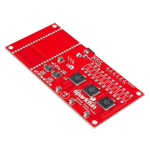
The ESP32 Power Control Shield offers a wide variety of options to control your next project. This shield enables the ESP32 Thing to switch up to 5A of a DC load between 5 and 28 volts.
Required Materials
The wish list below includes all of the materials that will be utilized in this tutorial:
Suggested Reading
If you aren't familiar with the following concepts, we recommend checking out these tutorials before continuing:
How to Solder: Through-Hole Soldering
Motors and Selecting the Right One
ESP32 Thing Hookup Guide
Beefcake Relay Control Hookup Guide
Hardware Overview
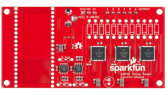
The ESP32 Thing Power Control Shield has a voltage range of 5-28VDC. Power can be connected in one of two ways. The first is the barrel connector, but with a maximum current rating of 2.5A it's really only meant for light loads. The second option is on the three pin screw terminal (rated at 6A), which has connections for VCC, ground, and a 5V output. The supply voltage is regulated down to 5V to power the ESP32 Thing, as well as a fan to keep the board cool under heavy loads.
At the heart of the board, is the MC33926 motor driver by NXP Semiconductors. The driver is capable of switching loads between 5-28VDC up to 5A. While the board is theoretically capable of switching up to 30A total, the power traces in the board and connectors have only been tested up to 10A total across the 6 outputs pins.
Along with switching DC loads on and off, the MC33926 also has three built in current sensors, which are connected to outputs 2, 4, and 6. Each of the current sensors are connected to a LMV358 operational amplifier to adjust the gain of each current measurement. For more details, refer to the Hardware Assembly section.
For a list of all connections to the ESP32 Thing, refer to the table below:
| ESP32 Thing Pin | Description |
|---|---|
| VUSB | 5V input to power ESP32 Thing. |
| 3V3 | 3.3V output to power MC33926 logic and LMV358 amplifiers. |
| GND | GND |
| 5 | Disable Outputs When HIGH, all outputs are have a high Z impedance. A 1 kΩ pull-down resistor enables all outputs by default. |
| 25 | Output 1 A logic HIGH pulls OUTPUT 1 to VCC and a logic LOW to GND. |
| 18 | Output 2 A logic HIGH pulls OUTPUT 2 to VCC and a logic LOW to GND. |
| 23 | Output 3 A logic HIGH pulls OUTPUT 3 to VCC and a logic LOW to GND. |
| 33 | Output 4 A logic HIGH pulls OUTPUT 4 to VCC and a logic LOW to GND. |
| 32 | Output 5 A logic HIGH pulls OUTPUT 5 to VCC and a logic LOW to GND. |
| 19 | Output 6 A logic HIGH pulls OUTPUT 6 to VCC and a logic LOW to GND. |
| 34 | Current Sense 2 0.24% of current on OUTPUT 2 |
| 39 | Current Sense 4 0.24% of current on OUTPUT 4 |
| 36 | Current Sense 6 0.24% of current on OUTPUT 6 |
Hardware Assembly
Soldering the pins
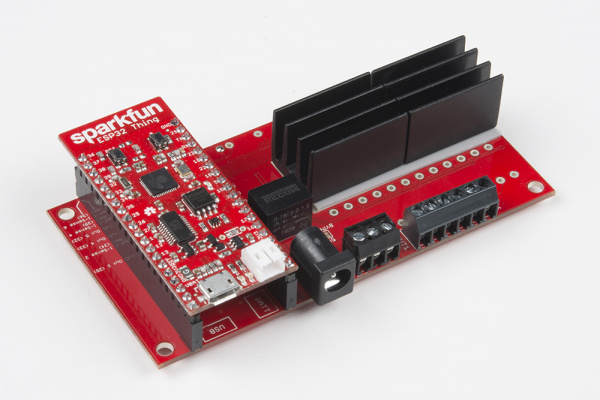
The first step in assembly is connecting the ESP32 Thing. Solder the male header pins from the top of the ESP32. Then solder the female header pins on the bottom side of the Power Control Shield. Make sure that the female header pin's sockets are facing out from the top side. The top side of the Power Control Shield will have the relay, barrel jack, and screw terminals. When connecting the ESP32, make sure to align it to the Power Control Shield's silkscreen for USB and BATT. These silk references correspond to the USB and battery connector on the ESP32 Thing. The correct orientation can be seen below after soldering the header pins.
Current Sense Gain
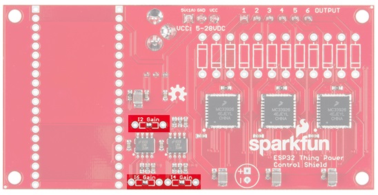
The MC33926 has a built in current sensor, which corresponds to 0.24% of the output current. Unfortunately, there is only one current sensor per driver which means current sensing is only supported on outputs 2, 4, and 6. For smaller loads, clearing the solder jumper with the iron and soldering in the appropriate feedback resistors for I2 gain, I4 gain, and I6 gain can maximize the sensitivity of the 12-bit analog to digital converter (ADC) built into the ESP32 Thing.
Use the table below for choosing the appropriate resistor values.
| Max Current (A) | Recommended Resistor (maximum value in Ω) |
|---|---|
| 5.0 | 2,800 |
| 4.5 | 4,300 |
| 4.0 | 6,200 |
| 3.5 | 8,800 |
| 3.0 | 12,200 |
| 2.5 | 17,300 |
| 2.0 | 24,800 |
| 1.5 | 38,500 |
| 1.0 | 69,000 |
| 0.5 | 238,000 |
Keeping the Drivers Cool
As VCC and the current draw increases, the driver ICs can get pretty hot due to the MOSFET’s resistance that do the actual switching between VCC and GND. MOSFETs are often described as switches. Unlike a normal switch, the resistance between the drain and source pins when the MOSFET is on, often referred to as Rds(on), is a bit higher than a mechanical switch (around 225 mΩ). It doesn't sound like much, but under full load the power that's wasted as heat can be as high as 5.6W! If your drivers are getting hot, add a heat sink to the back of the board like the image shown below.
If heat sinks aren't able to pull the heat away fast enough, you may also need a fan. If your supply voltage is 12V, a standard computer fan should work. If it's not and you don't want to use two supplies, the 5V rail has been broken on on 3-pin screw terminal for a 5V fan, and it is capable of sourcing up to 1A of current.
5V Bypass Jumper
A linear regulator (like the LM7805), can regulate any DC voltage from 7 to 35V down to 5V. If your supply drops below 7V, the output voltage will follow the input voltage up to 5V. To minimize the heat dissipation, a high efficiency DC-DC converter was used on the Power Control Shield to regulate the supply voltage down to 5V for powering the ESP32 Thing. Unfortunately, the output from the DC-DC converter will not turn on like a linear regulator if the input voltage drops below the minimum voltage. With the ESP32 Thing Power Control Shield, that minimum voltage of 7V and any voltage under that is not guaranteed to be sufficient for providing power to the ESP32.
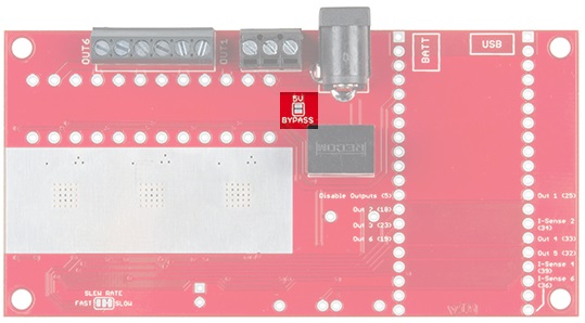
What if the load needs to be at 5V? In that case, you should use the 5V bypass jumper that is shown in the image below.
When soldered closed, the jumper shorts the VCC and 5V power rails together, allowing you to bypass the regulator and power the ESP32.
Slew Rate
The slew rate jumper on the top of the board has two configurations to control how fast the output pins switch between on and off. The default mode has the solder jumper set to SLOW and it typically takes 3.0 us to switch states. You can cut the trace and add a solder jumper to switch to FAST mode. When the board is set to FAST, it can switch the state anywhere from 0.2 us to 1.45 us. If you are not using an inductive load (such as a motor), the default slow slew will create smaller current spikes when the load switches on or off.
The Unpopulated Parts
You may have noticed that there are quite a few unpopulated through hole parts on the board. The first three to mention are the resistors labeled I2 Gain, I4 Gain, and I6 Gain. These are the feedback resistors used in the non-inverting op-amps circuits that are discussed in detail in the Current Sense Gain section above.
Next is the capacitor connected to VCC and GND. As inductive loads (such as motors) turn on, there is a large current spike to charge the coils which can pull the supply voltage low enough that the power supply to the ESP32 Thing shuts off which can cause the microcontroller to reset. To keep the input voltage steady, you can add a large capacitor. The right capacitor depends on the size of the load, but any electrolytic capacitor larger than 100 μF should help. The pin spacing should be 2.5 mm, and the voltage rating should be at least the same as your supply voltage. Although, it's good practice to use parts that are rated for 1.5 times the voltage you expect.
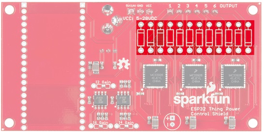
Lastly, there are 12 unpopulated diodes that are connected to either VCC or GND, and the output pins. The diode footprints are there for people that are planning on using inductive loads. As an inductor discharges, there can be a large voltage spike. If the spike is large enough, it can possibly damage the MC33926 driver. For that reason, it's recommended to pick up and install 12 of our 1N5819 or 1N4001 diodes.
Software
Now that the shield is assembled, the only thing left to do is to throw some code on the ESP32!
LED Strips
LED strips have gained a lot of popularity in the last few years, from task lighting, to computer cases, and even home theater lighting. In this section, we'll explore how you can use the ESP32 Thing with a Power Control Shield to control your LED strips.
For this example, we'll be using the non-addressable LED strips (either 1m strip or 5m strip will do the trick). Because each strip has a red, green, and blue pin, you could easily connect two strips to the shield for different patterns at the same time. In this example, VCC is set to 12V. Start by connecting the 12V black wire of the LED strip to the screw terminal labeled VCC. Then connect the red wire to Output 1, green wire to Output 2, and the blue wire to Output 3. Upload the example code below to the ESP32. Once uploaded, you will be able to see the LEDs changing colors.
language:c
// Connect the BLACK wire to VCC (12V)
#define CTRL_1 25 // Output 1 (RED)
#define CTRL_2 18 // Output 2 (GREEN)
#define CTRL_3 23 // Output 3 (BLUE)

void setup() {
  // Initialize pins
  pinMode(CTRL_1,OUTPUT);
  pinMode(CTRL_2,OUTPUT);
  pinMode(CTRL_3,OUTPUT);

  // Assign the control pins to PWM channels 0-2
  ledcAttachPin(CTRL_1, 0);
  ledcAttachPin(CTRL_2, 1);
  ledcAttachPin(CTRL_3, 2);

  // Initialize PWM Channels
  // ledcSetup(uint8_t channel, uint32_t frequency, uint8_t bit_resolution)
  ledcSetup(0,10000,8);
  ledcSetup(1,10000,8);
  ledcSetup(2,10000,8);
}

void loop() {
  int rgb[] = {255, 255, 255};

  // ledcWrite(channel, duty)
  ledcWrite(0,rgb[0]);
  ledcWrite(1,rgb[1]);
  ledcWrite(2,rgb[2]);

  for(int i=0;i<255;i+=5)
  {
    rgb[0] = 0;
    rgb[1] = 255 - i;
    rgb[2] = 255;
    ledcWrite(0,rgb[0]);
    ledcWrite(1,rgb[1]);
    ledcWrite(2,rgb[2]);
    delay(25);
  }

  for(int i=0;i<255;i+=5)
  {
    rgb[0] = i;
    rgb[1] = 0;
    rgb[2] = 255;
    ledcWrite(0,rgb[0]);
    ledcWrite(1,rgb[1]);
    ledcWrite(2,rgb[2]);
    delay(25);
  }

  for(int i=0;i<255;i+=5)
  {
    rgb[0] = 255;
    rgb[1] = 0;
    rgb[2] = 255 - i;
    ledcWrite(0,rgb[0]);
    ledcWrite(1,rgb[1]);
    ledcWrite(2,rgb[2]);
    delay(25);
  }

  for(int i=0;i<255;i+=5)
  {
    rgb[0] = 255;
    rgb[1] = i;
    rgb[2] = 0;
    ledcWrite(0,rgb[0]);
    ledcWrite(1,rgb[1]);
    ledcWrite(2,rgb[2]);
    delay(25);
  }

  for(int i=0;i<255;i+=5)
  {
    rgb[0] = 255 - i;
    rgb[1] = 255;
    rgb[2] = 0;
    ledcWrite(0,rgb[0]);
    ledcWrite(1,rgb[1]);
    ledcWrite(2,rgb[2]);
    delay(25);
  }

  for(int i=0;i<255;i+=5)
  {
    rgb[0] = 0;
    rgb[1] = 255;
    rgb[2] = i;
    ledcWrite(0,rgb[0]);
    ledcWrite(1,rgb[1]);
    ledcWrite(2,rgb[2]);
    delay(25);
  }
}
Motor Control Current Sensing
This code allows you to control a motor using the current sensor connected to output 2. For this example, we we will be using a 90 RPM micro gearmotor with a wheel. We will be connecting VCC to a 12V power supply. Prepare the micro gearmotor by soldering wires to the terminals. Then attach the wheel to the shaft. Connect the wire that is attached to the "+" pin to OUTPUT 2. Connect the other wire to OUTPUT 1. Upload the code below to the ESP32.
language:c
#define CTRL_1 25 // Output 1 (Motor -)
#define CTRL_2 18 // Output 2 (Motor +)

void setup() {
  // Initialize UART
  Serial.begin(115200);

  // Initialize pins
  pinMode(CTRL_1,OUTPUT);
  pinMode(CTRL_2,OUTPUT);
}

void loop() {
  int adcVal = 0;
  boolean runMode = 0; // 0-Stop, 1-Run

  while(runMode == 0) // Forward
  {
    // Turn motor on
    digitalWrite(CTRL_1,LOW);
    digitalWrite(CTRL_2,HIGH);
    delay(250); // delay to prevent current spike from giving a false positive on the ADC

    // Sample I-Sense 2
    adcVal = analogRead(34);
    Serial.println(adcVal);

    if(adcVal > 100)
    {
      runMode = 1;  // Reverse
    }
  }

  // Stop motor
  digitalWrite(CTRL_1,LOW);
  digitalWrite(CTRL_2,LOW);
  delay(2000);

  while(runMode == 1) // Reverse
  {
    // Turn motor on
    digitalWrite(CTRL_1,HIGH);
    digitalWrite(CTRL_2,LOW);
    delay(250); // delay to prevent current spike from giving a false positive on the ADC

    // Sample I-Sense 2
    adcVal = analogRead(34);
    Serial.println(adcVal);

    if(adcVal > 100)
    {
      runMode = 0;  // Forward
    }
  }

  // Stop motor
  digitalWrite(CTRL_1,LOW);
  digitalWrite(CTRL_2,LOW);
  delay(2000);
}
When we hold the motor with one hand, and the spinning wheel with the other, the motor will draw more current as the motor slows down. Too much current, and the motor will stop, wait for two seconds, spin in the opposite direction, and repeat. By opening a serial monitor set to 115200, we can also observe the changes in current as the motor increases the torque. Without a feedback resistor for I2 Gain, the motor draws a small enough current, that the ADC value should be close to 0. When the torque increases, the current increases as well which results in a ADC value greater than 100. In robotics and home automation, measuring the current being delivered to a motor can provide a lot of information, like being stuck.
Resources and Going Further
Now that you've successfully got your ESP32 Power Control Shield up and running, it's time to incorporate it into your own project!
For more information, check out the resources below:
- ESP32 Thing Power Control Shield Schematic
- Eagle Files
- MC33926 Datasheet
- SparkFun ESP32 Thing Power Control Shield Github Repo
Need some inspiration for your next project? Check out some of these related tutorials:
