Designing PCBs: SMD Footprints
 Nate
Nate 
Symbol Creation
Eagle requires three things to get an IC into the library:
- Package (also known as a footprint)
- Symbol (the schematic symbol)
- Device (mapping them together)
The tutorial images show us working from the SparkFun-DigitalIC.lbr file but you can create your own custom library file if you'd like.
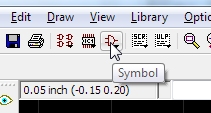
It's time to create the schematic symbol. Click on the ‘symbol’ button.
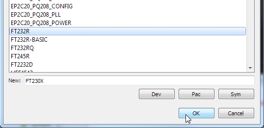
Now give this symbol a name. We are creating the schematic component for the FT230X, and we see that we don’t have another symbol with that name, so let’suse it!
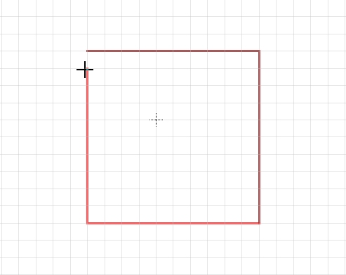
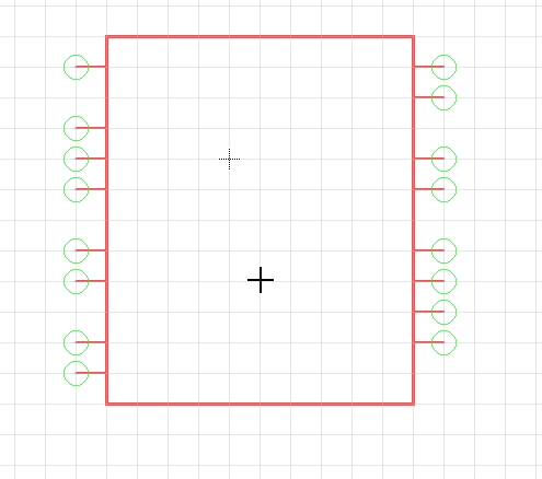
Start by clicking on 'Wire' and drawing a square box. Press escape to stop drawing.
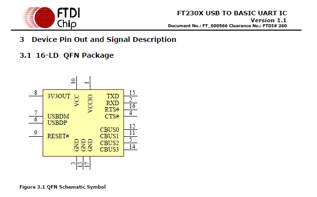
Now how many functional pins does the FT230X have? I ask about ‘functional’ pins because some ICs have pins that are not labeled or labeled as NC (Not Connected). I generally don’t show NC pins on my schematic symbols as they can clutter things up. In the case of the FT230X, all 16 pins have a function.
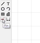
You’ll find the ‘pin’ button on the left menu. Click it.
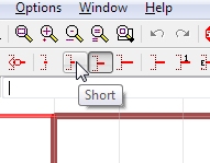
Once you’ve are in ‘pin’ mode you’ll get a different menu at the top of the screen. Click on ‘short’ to shorten the length of this pin indicator. I do this to save space. Now place 16 pins around the box.
Time to save your work! Hit the disk or Ctrl+s.
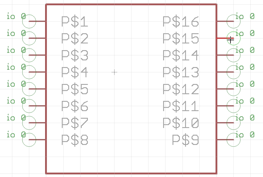
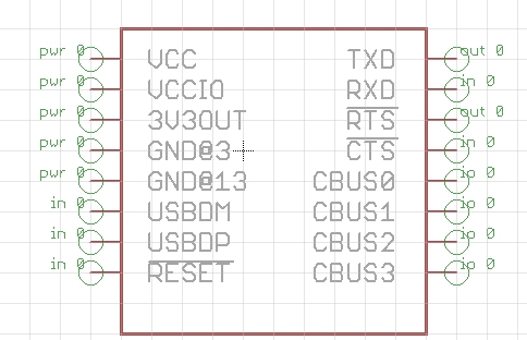
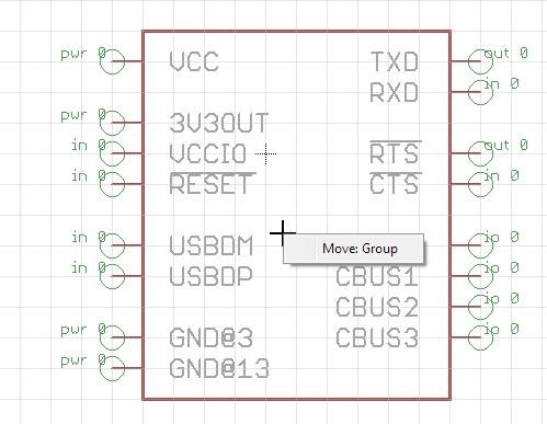
That is one ugly schematic symbol. Now let’s name each pin. Press F4 to go into naming mode and then click on the first pin P$1.
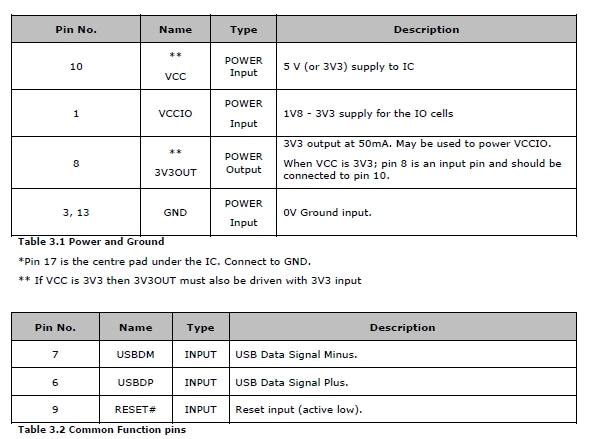
I am going to start at the top of the list with VCC and work my way down the datasheet list so that I don’t miss any. Note that there are two GND pins (3 and 13) so make two pins with that name.
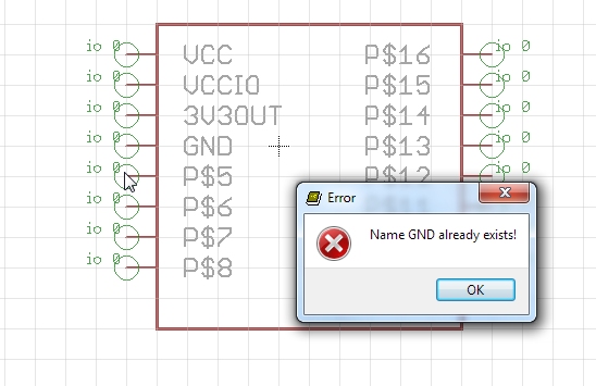
Oh no! You cannot name two pins with the same name. To get around this Eagle allows you to name pins with the @ sign. So name the first GND pin GND@3 (meaning GND pin at pin 3). And the other GND@13. You’ll see this come into play when we are mapping the schematic symbol to the pads on the package.
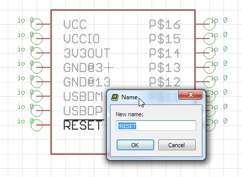
The reset pin is named RESET# which is short hand for 'active low'. Another way to say this is the IC is reset when the pin is pulled low.
A trick in Eagle: if we put a ‘!’ before the pin name it will put a line over the pin (a line over a pin name is another short hand way to indicate it is active low). This doesn’t have any effect on the overall part or layout, it just looks nice and helps us remember this pin is an active low pin. Do the same for RTS and CTS.
We’ve now got our pins labeled.
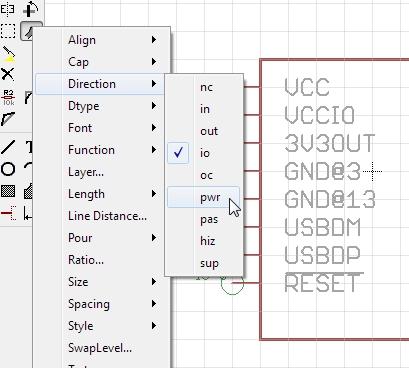
Now we can define each pin type. pwr is good for VCC and GND pins. You can also define inputs and outputs. When in doubt, I leave the pin as the default ‘io’.
Now the pins have direction. These signifiers can help the DRC (design rule check) and ERC (electrical rule check) to detect potential problems with your board. For example, an output is usually not hooked up to another output so the ERC will throw an warning if it detects to output pins connected together.
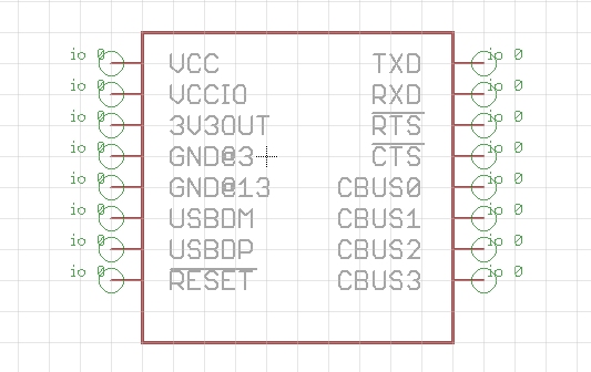
Now hit the F7 button to go into ‘move’ mode. I like to arrange the power and configuration pins on the left side of the symbol and the user accessible pins on the right side.
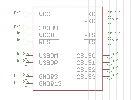
I chose this configuration for a couple reasons:
- Reset is generally tied high to 3V3OUT so I put them near each other.
- VCCIO can be tied to 3V3OUT or VCC (most commonly 3V3OUT) so it is near VCC and 3V3OUT.
- USBDM is a net that is usually above the USBDP net when connecting it directly to a USB connector. You wouldn’t know this until you lay out a handle of schematics with USB and have to cross the USB+ and USB- nets to get them going into the other component. It’s easier just to put the USBDM pin above the USBDP pin.
- All pins are sort of spread out in groups of what they do. TX and RX and the major pins - top right. Next CTS/RTS get used much less but are often used together. The very neat, but option CBUS pins are off by themselves.
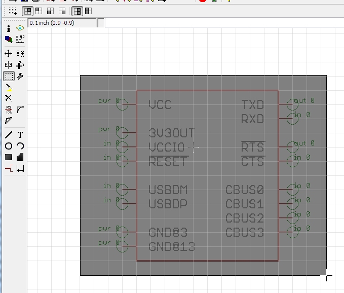
Now let’s center this beast. Hit Alt+F7 to go into ‘group’ mode. Place the cursor in top left corner. Click the mouse and hold, then drag the square to the lower right corner. Release the mouse.
Note how everything is highlighted. You’ve selected all the parts of this schematic symbol.
Now, hold ctrl and right click. You will see the entire group begin to move.
Alternatively (and for you Apple folks without a ctrl key) you can right click then click on the Move:Group menu option. I vastly prefer the ctrl+right click method as it saves you a step.
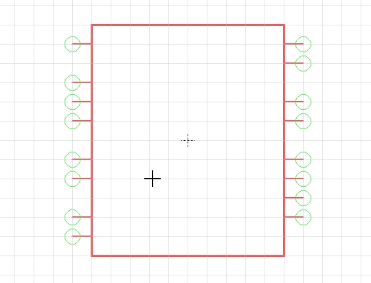
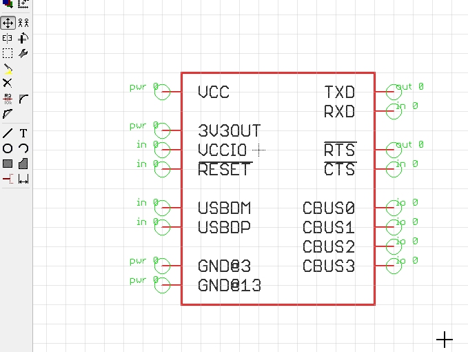
Now move the entire group so that the origin sign (the smaller +) is in the middle of your part. If your part happens to be oblong in one direction, that’s ok, just get it close to the center.
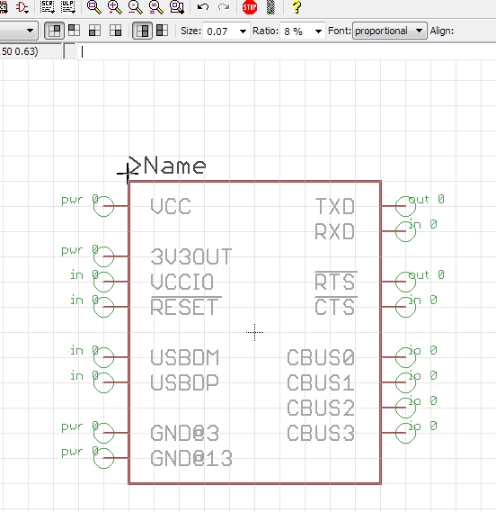
Remember the weird >Name and >Value thing when you created your package? We need to do that again! Click on the ‘text’ button. Type ‘>Name’ and press enter. Before placing the text, click your scroll wheel and goto the >Names layer.
I did a couple things before left clicking the mouse and dropping the text into place:
- Increased the text size to 0.07
- Held alt while moving my text so that it is not right up against the border of our part. Makes it easier to read when we create PDFs and print schematics.
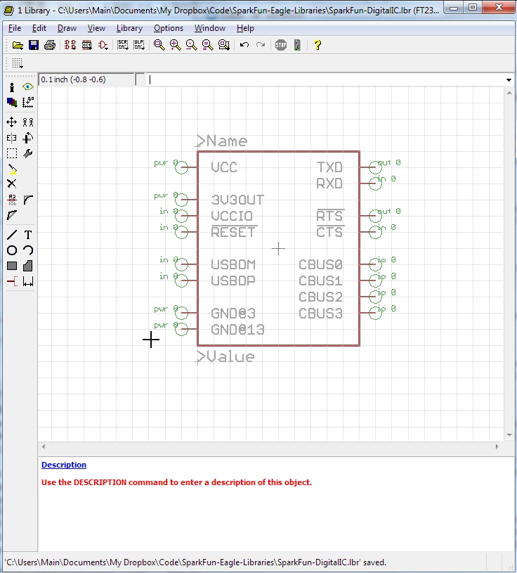
Repeat for >Value. Save your work!
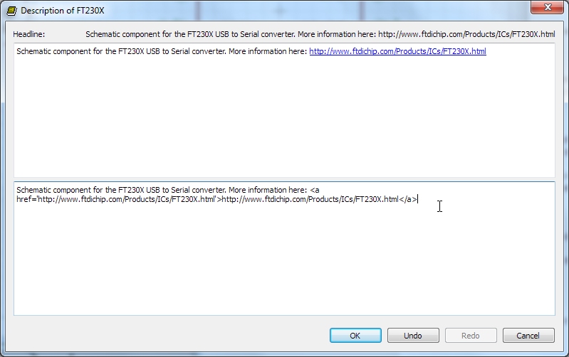
Be sure to add a description to your part. Check it out! We can add some basic HTML markup if we want!
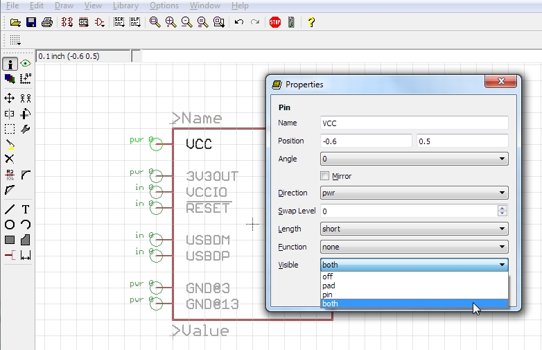
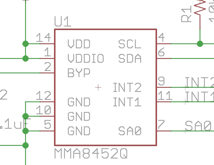
Click on the 'i' then on a given pin. By default, every pin has the ‘Visible’ option set to ‘both’. This means both the number assigned to this pin and the pad fuction will be displayed. This will show on your schematic like this:
It depends on the part, but I often think showing the pin numbers is more information than is needed and begins to make the part look cluttered. For example, we don’t need to know that the BYP pin on this device is also pad 2 on the IC footprint, we just need to know that this connection point is for the bypass cap.
To turn this off, we set the ‘Visible’ option to ‘pin’ on each pin.
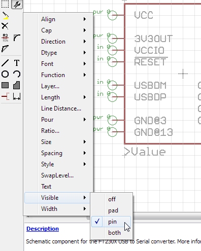
Click on the ‘change’ wrench, Visible, then pin. Then click on each pin. You won’t see anything change on the schematic component but it will be reflected on your overall schematic.
Hit save and you’re done! Next we move on to Device creation.