Decade Resistance Box Hookup Guide
 Byron J.
Electrical Assembly
Bill Of Materials
Before we start soldering, let's verify that all of the parts are present in the kit.
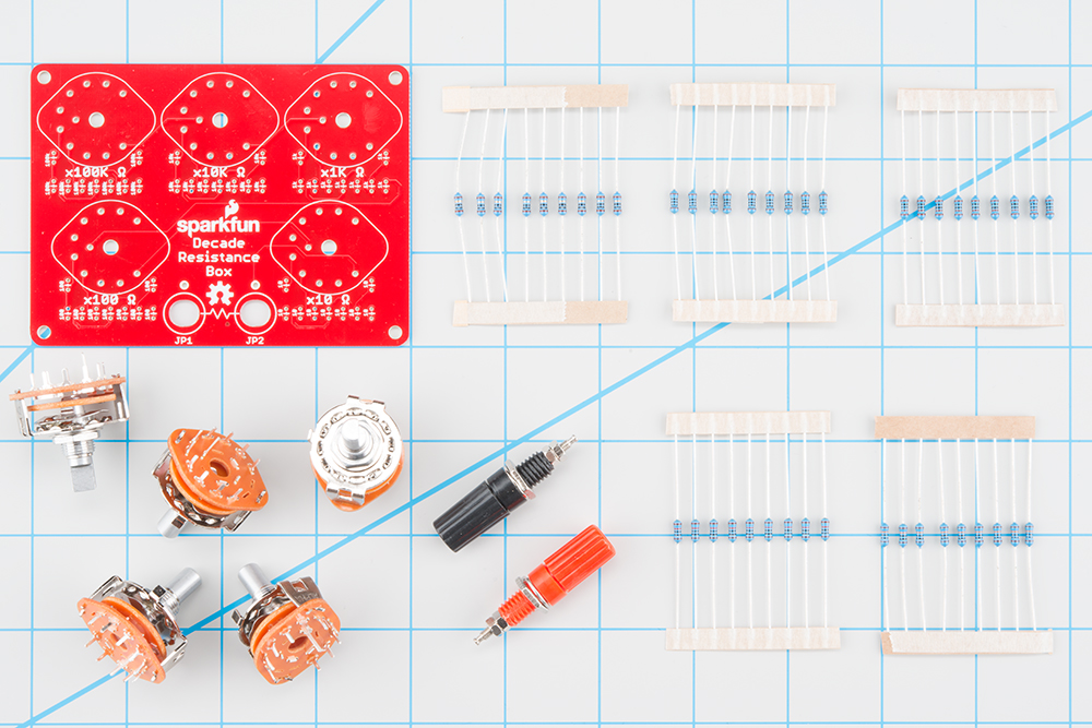
As shown above, you should have the following (clockwise from top-left)
- One Decade Resistance Box PCB
- Nine 10 Ω Resistors (Brown - Black - Black - Gold - Brown)
- Nine 100 Ω Resistors (Brown - Black - Black - Black - Brown)
- Nine 1000 Ω Resistors (Brown - Black - Black - Brown - Brown)
- Nine 100K Ω Resistors (Brown - Black - Black - Orange - Brown)
- Nine 10K Ω Resistors (Brown - Black - Black - Red - Brown)
- One red banana jack
- One black banana jack
- Five 1-pole 10-position rotary switches, each with a dress washer and hex nut
Electronic Assembly
For the most part, the assembly of the decade resistance PCB is straight forward. We'll cover a few extra tips and tricks as we go along.
The first thing to note is that the PCB has definite top and bottom sides. The components are placed on the top of the board, which is marked with symbols for each component - tick marks for the resistors, and oblong outlines for the rotary switches. The components are soldered to the back of the board. The copper solder pads are only exposed on the back side - if you're having trouble getting the solder to stick, doublecheck that you're working on the correct side.
Soldering Resistors
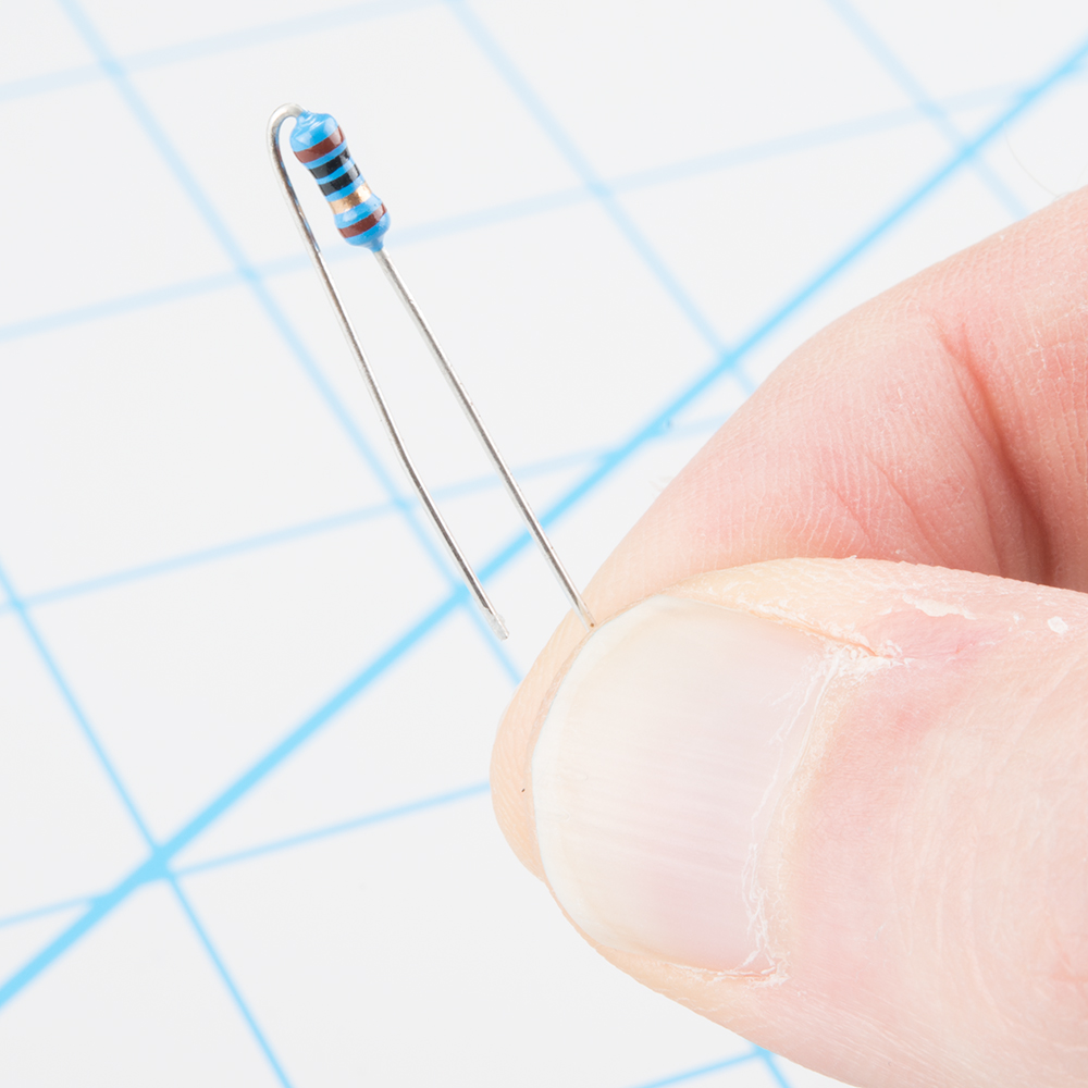
Unlike many other soldering kits where the resistors lie flat on the PCB, the resistors on the decade resistance will be installed in a "standing up" orientation. This saves space on the PCB, and is commonly used in devices like guitar pedals and transistor radios.
To fit the resistor to the board, bend one lead sharply at the end of the body, doubling back 180°, so the overall result looks like a hairpin.
Then insert the resistor into the board, and splay the leads so they hold it in place while you solder.
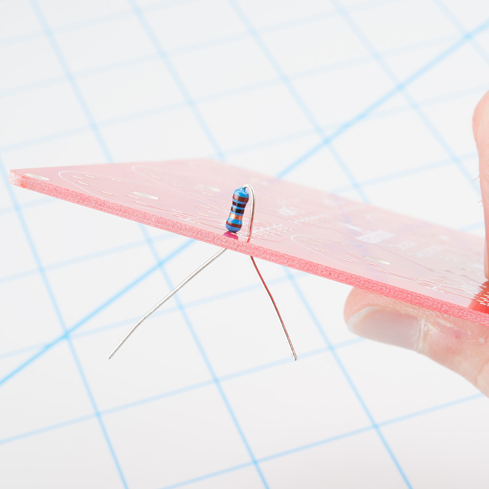
After soldering each resistor, trim the leads close to the solder fillet.
There are nine pieces of each of five different resistance values in the kit. Each value will be installed adjacent to each rotary switch. Each row is labeled with the value to be installed there.
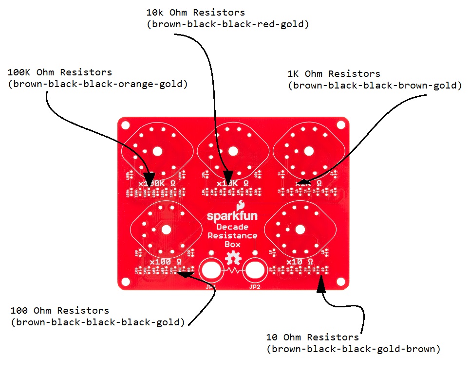
If you're unsure about reading the stripes on the resistors, you can use a multimeter to verify their value.
Soldering Rotary Switches
After the resistors are in place, install the rotary switches. The rotary switches fit within the matching outlines on the board. The footprint is slightly asymmetrical, so they only fit the PCB in one orientation.
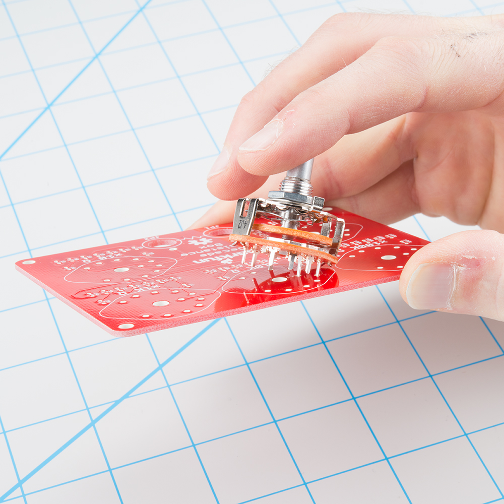
The five switches are all the same, and interchangable on the PCB. Insert them into the footprint, and solder all eleven leads in place. If you're going to put the decade box in an enclosure, ensure that the switches sit flat on the surface of the board before soldering.
Finally, the center pin of each rotary is longer than the others. You can snip this off with cutters after soldering.
Binding Posts
If you're installing the decade resistance in an enclosure, skip ahead to the next section. You'll mount the jacks to the enclosure, rather than the PCB!
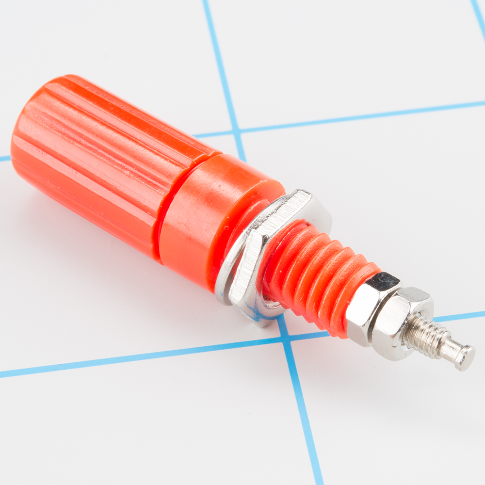
Before we install them, let's take a moment to look at how the banana jacks go together. The back side of the jack is threaded, with a large nut that holds the jack in place. However, this only provides the mechanical mounting of the jack. If you look closely, there are a pair of smaller nuts on the tail of the jack. The outer of these nuts is for electrical connection, and the inner nut holds the jack together. To use the jack, we first need to make sure that the inner nut is snug against the body so the jack doesn't come apart. We'll then use both the mounting and electrical connections.
Even though there are red and black jacks, the decade box has no specific polarity - it doesn't matter which one is mounted in which hole. The color coding is just a convention that can be useful to trace connections on a busy workbench.
First, remove the larger nut from the jack, then insert the jack through the PCB, and reinstall the nut. Take care to not over-tighten, or you can strip the plastic threads.
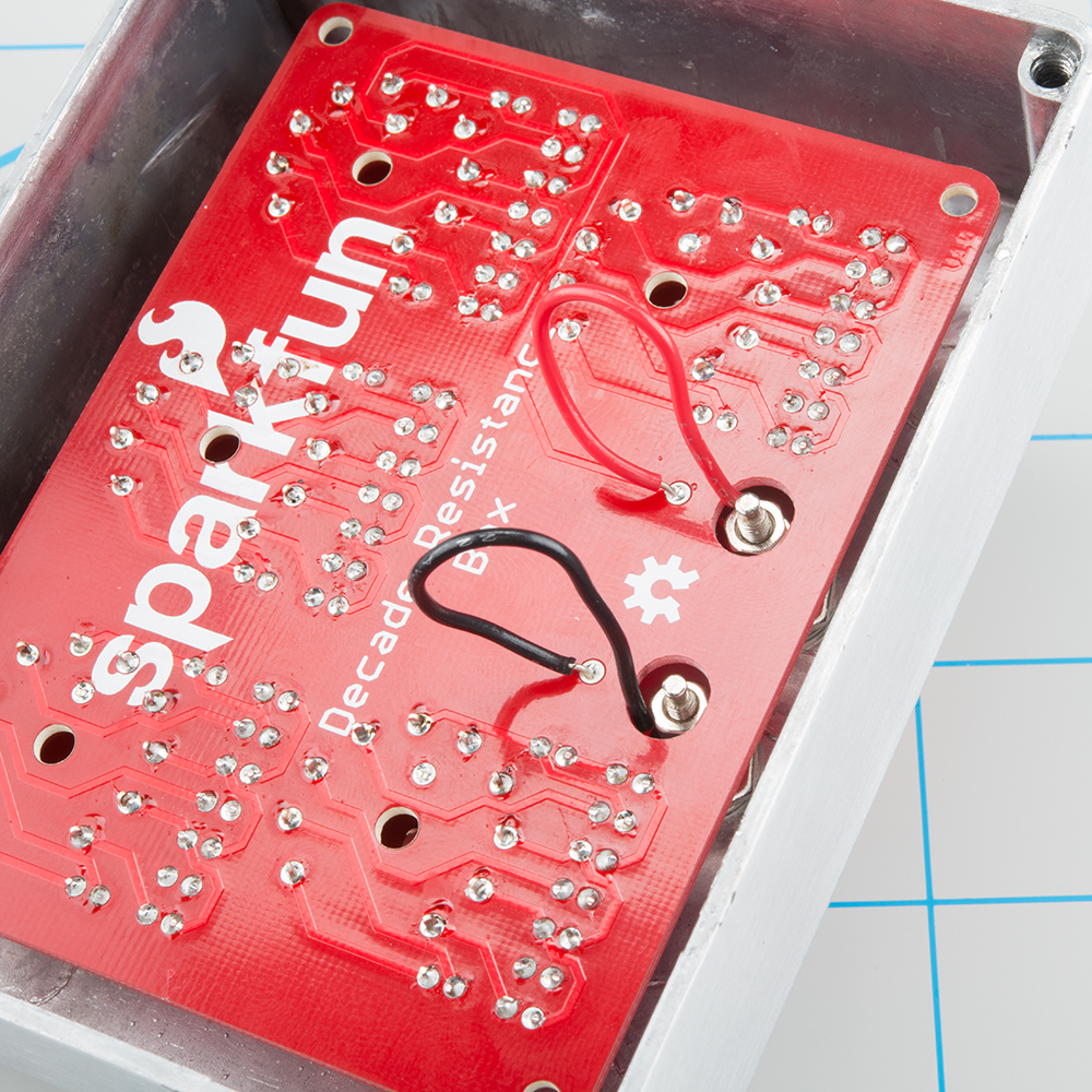
Once the jack is securely mounted, take a 2 inch piece of solid-core wire, and strip the ends. Bend one end into a question-mark shaped curl.
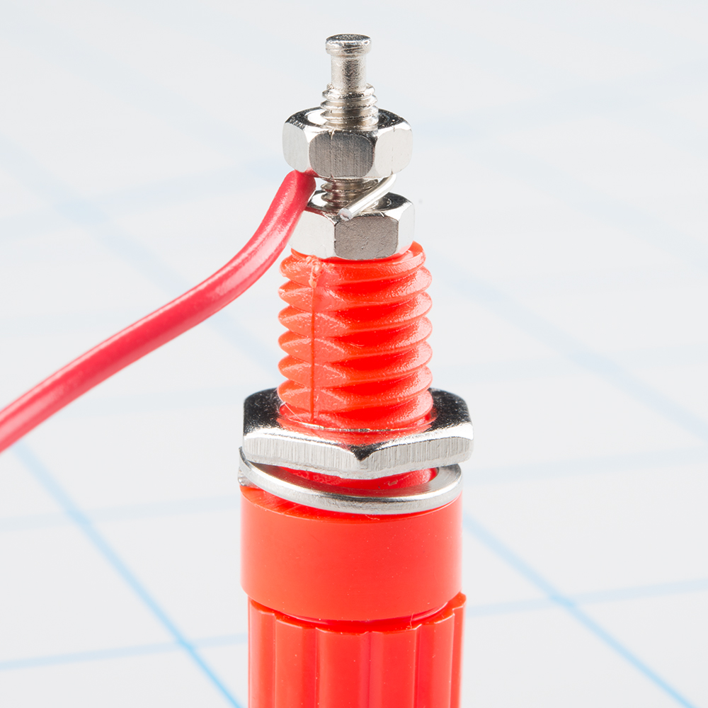
Loop the curl around the metal end of the binding post, and tighten the small nut to hold it in place. This is much easier to do if the curl points in the clockwise direction. Otherwise, tightening the nut will cause the wire to uncurl and come off the post.
With the wire secured to the post, solder the other end of the wire to the nearby PCB pad.
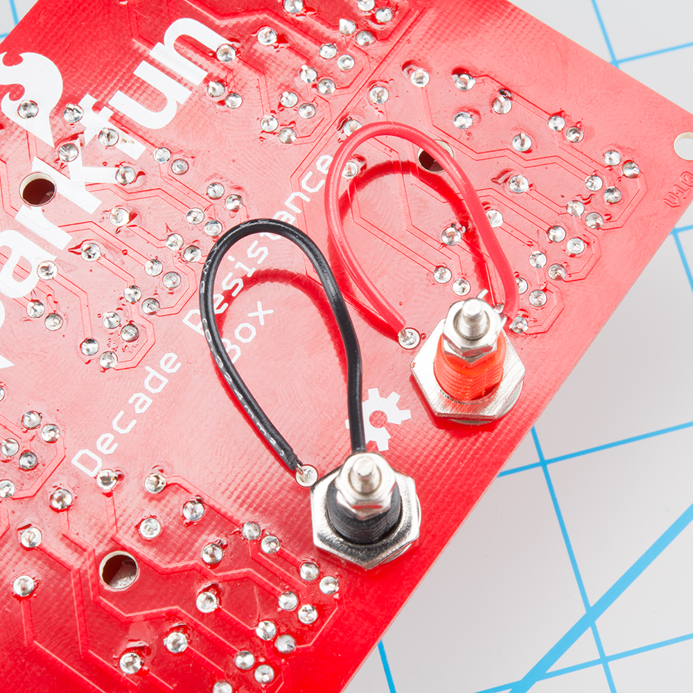
With the first jack mounted, repeat this for the other jack.
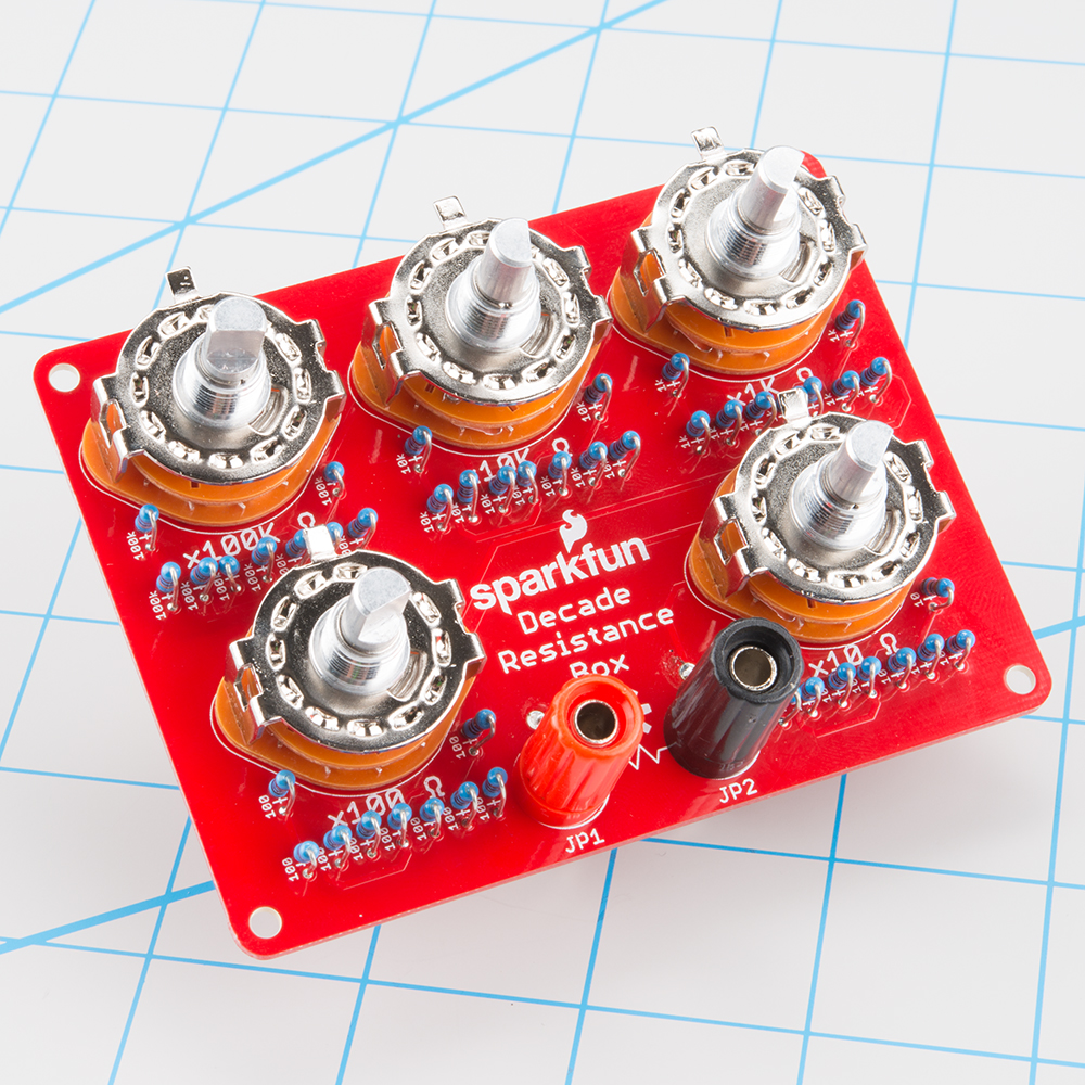
With all of this complete, your decade box should look like this
Installation In Enclosure
If you have opted to put your kit in an enclosure, the assembly changes a bit.
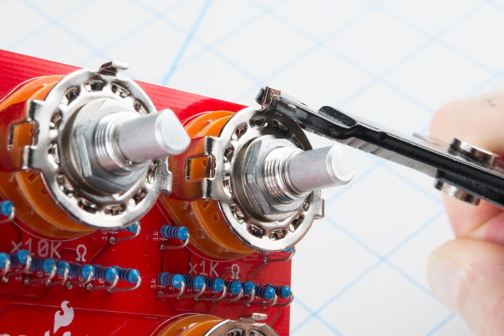
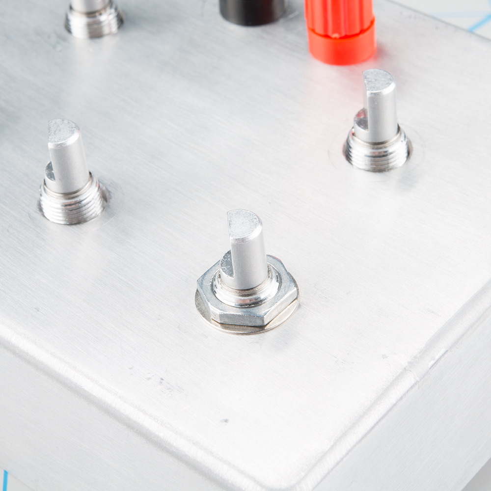
First, the rotary switches have an alignment tab that sticks up, and prevents them from mounting flush behind the panel. With a small pair of pliers, simply bend the tab so the switch body lies against the backside of the panel.
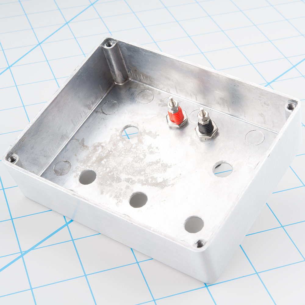
The binding posts are also mounted somewhat differently. Secure them to the panel of the enclosure, rather than the PCB.
Then install the wires on the back of the binding posts. Run the wires through the oblong holes in the PCB, and solder them in place.
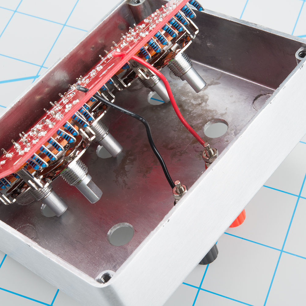
Carefully pull the wire slack through the holes, as you slide the PCB into the enclosure. The rotary switches will protrude through the corresponding holes in the enclosure, and the tails of the binding posts will barely stick through the oval holes in the PCB.
Secure the PCB in the box by mounting each rotary switch with the dress washer and hex nut. You can use pliers or a 12mm socket to tighten the nut.
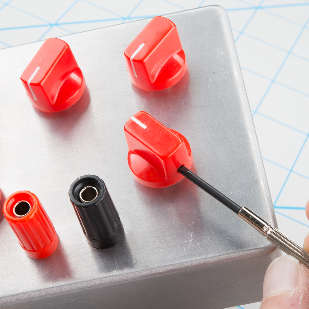
Finally, put the back on the enclosure, and attach the knobs. If you're using the knobs recommended above, the set screw will tighten against the flat side of the shaft, 180° opposite the indicator.
Quick Test
With the assembly complete, you can give the decade resistance a quick test with a multimeter. Select the resistance scale on the meter, and measure between the binding posts.
With five switches that can each take ten positions, there are 100,000 combinations! We couldn't call this section a "quick test" if we were going to try to hit all possible settings, so we'll use a streamlined approach instead. We'll verify that every switch and every resistor is properly installed and functional. If they're right in isolation, we can extrapolate that they'll be right in combination.
- Start with all of the rotary switches at zero. You should measure close to zero ohms on the meter.
- Select the 10's position switch, and click it through each of it's steps. The meter should read an additional ten ohms for each click of the switch.
- After you have measured the top position (90 Ω), reset the switch to zero.
- Repeat the above steps for each of the other rotary switches.
A Note On Accuracy
It's worth mentioning that the meter readings in the above test will not absolutely match the settings on the decade box. For instance, the 90 Ω setting might read as 89.3 or 90.5 - very close to the ideal value, but not perfect. There are a couple factors that contribute to this.
- First, there is a tiny amount of intrinsic resistance in the circuit. The leads of the multimeter, the traces of the PCB, and other components are not ideal conductors, and exhibit a small amount of "parasitic resistance." In practice, it's small enough to be negligible. If the all zero setting is higher than an Ohm or two, doublecheck your work.
- Second, the resistors in the decade resistance also have a small amount of variability - they're rated to be within +/- 1% of the given value. There are 0.1% tolerance resistors, but they are significantly more expensive than the 1% ones.
- Third, the accuracy and precision of the multimeter itself will show some variance.