Decade Resistance Box Hookup Guide
Introduction
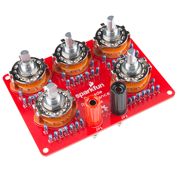
A decade box is a tool that contains resistors of many values accessed via mechanical switches. Adjust the knobs to output any of the discrete resistances offered by the box.
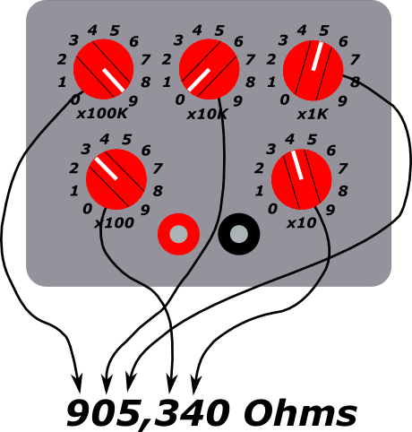
They are known as decade boxes because they have controls that correspond to the digits in a decimal number - a control for the tens position, a control for the hundreds position, and so on.
Traditional decade boxes looked like something out of Dr. Frankenstein's lab - large wooden enclosures, with engraved front panels and big Bakelite knobs. They were available in three main types - resistance, capacitance and inductance. This kit is for a decade resistance box. It allows you to quickly and accurately dial in a specific resistance value between 0 and 999,990 Ω, in 10 Ω increments..
In this hookup guide, we'll first assemble the decade box, then explore its application as a design aid and a test instrument.
Necessary Tools
- Soldering Iron
- Lead-based or Lead-free solder
- Diagonal or Flush cutters
Additional Tools and Supplies
- Red or black knobs are highly recommended - the rotary switches are very hard to turn without knobs!
- A small set of pliers
- Small Philips Screwdriver
- A few inches of solid core hookup wire.
- Safety Glasses
- Magnifying glass or Loupe
- PCB Vise or Third Hand
- Volt Meter
Optional Materials
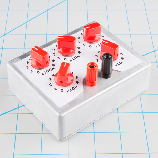
The decade box can be assembled to fit in an enclosure or behind a front panel. In this tutorial, we'll build it into a cast aluminum enclosure.
If you want to build yours into an enclosure, you'll need the following.
- Aluminum enclosure
- Removable tape, such as painter's or gaffer's tape
- Center Punch and hammer
- A vise or clamps
- A drill press or hand drill
- A set of drill bits, or a step-drill
Suggested Reading
If you aren’t familiar with the following concepts, we recommend checking out these tutorials before continuing.
How to Solder: Through-Hole Soldering
Connector Basics
Voltage, Current, Resistance, and Ohm's Law
Resistors
Button and Switch Basics
Electric Power
How to Use a Multimeter
Also, it is recommended to check out this tutorial on enclosure modification:
 |
| Tutorial for Enclosure Modification |
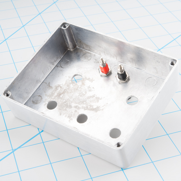
Enclosure Drilling
The decade resistance can be mounted in an enclosure, or used without one. If you want to put it in an enclosure, it is easiest to prepare the enclosure before the board is assembled.
If you aren't going to use an enclosure, you can skip ahead to the next section.
For this guide, we'll be using a small aluminum enclosure, because they are durable, and aluminum is easy to drill.
Marking
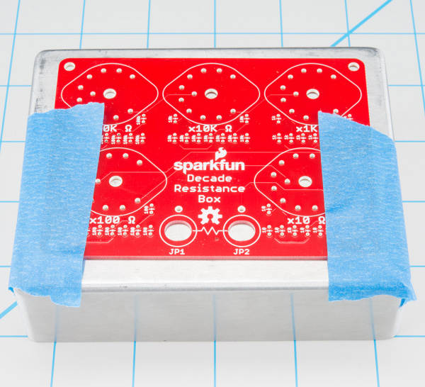
The PCB for the decade resistance does double duty as a drilling template. Each of the holes needed in the enclosure has a matching hole in the PCB.
To use the template, tape the PCB onto the enclosure, with equal spacing to each edge.
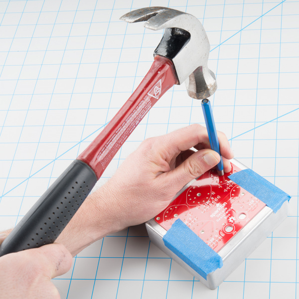
Mark the center of each of the holes with a center punch. Tap it with a hammer so it leaves a small divot - the divot will serve to guide the bit when you start drilling. There will be five marks for the rotary switches, and two more for the banana jacks.
The oval holes for the banana jacks won't be as precise a guide for the punch - it's OK to gauge the center of those holes by eye.
Drilling
Before we start drilling, let's take a moment to review some basic drilling safety practices, which apply whether you're using a hand drill or a drill press.
Drilling aluminum produces small, sharp pieces of metal ("curliqueues" or "chips" as machinists call them). Safety glasses or a face shield are essential, and work gloves help protect your fingertips.
The bit can bind in the material, and cause the box to spin on the end of the bit. This is dangerous, as it can damage the box, the bit, and your fingers. Secure the box with a vise or clamps before drilling!
A little lubricant can help the bit cut more smoothly, and prevents dulling. There are specialty machinist's bit lubricants, but if you don't have them handy, a few drops of light household oil will help.
If you're using regular bits, start with smaller ones, then work up to larger ones. We began with a 1/8" bit to make pilot holes on each of the center punch marks, then worked progressively up to larger bits. The five holes for the rotary switches should be drilled to 3/8".
The two banana connectors fit in 5/16" holes. Lacking a 5/16" bit, we drilled them to 1/4", then filed the holes until the connectors fit.
If you're not enthusiastic about all of those bit changes, consider using a stepped drill bit, such as the Irwin Unibit.
Once the holes are drilled, consider using a countersink to deburr and bevel the holes, to remove any sharp edges left by the drilling.
Labeling
In the decade box GitHub repository, there is an SVG file of the panel legend. If you have access to a laser engraver, you can etch it into the enclosure.
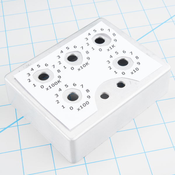
If you aren't lucky enough to have access to a laser cutter, you can simply print it on paper, trim it to fit, and stick it on with adhesive tape.
Electrical Assembly
Bill Of Materials
Before we start soldering, let's verify that all of the parts are present in the kit.
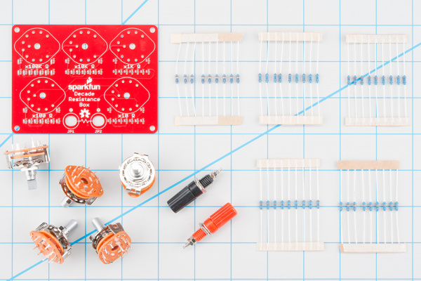
As shown above, you should have the following (clockwise from top-left)
- One Decade Resistance Box PCB
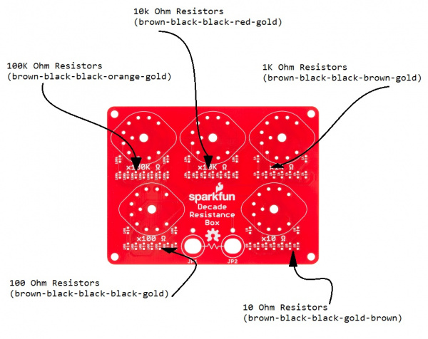
- Nine 10 Ω Resistors (Brown - Black - Black - Gold - Brown)
- Nine 100 Ω Resistors (Brown - Black - Black - Black - Brown)
- Nine 1000 Ω Resistors (Brown - Black - Black - Brown - Brown)
- Nine 100K Ω Resistors (Brown - Black - Black - Orange - Brown)
- Nine 10K Ω Resistors (Brown - Black - Black - Red - Brown)
- One red banana jack
- One black banana jack
- Five 1-pole 10-position rotary switches, each with a dress washer and hex nut
Electronic Assembly
For the most part, the assembly of the decade resistance PCB is straight forward. We'll cover a few extra tips and tricks as we go along.
The first thing to note is that the PCB has definite top and bottom sides. The components are placed on the top of the board, which is marked with symbols for each component - tick marks for the resistors, and oblong outlines for the rotary switches. The components are soldered to the back of the board. The copper solder pads are only exposed on the back side - if you're having trouble getting the solder to stick, doublecheck that you're working on the correct side.
Soldering Resistors
Unlike many other soldering kits where the resistors lie flat on the PCB, the resistors on the decade resistance will be installed in a "standing up" orientation. This saves space on the PCB, and is commonly used in devices like guitar pedals and transistor radios.
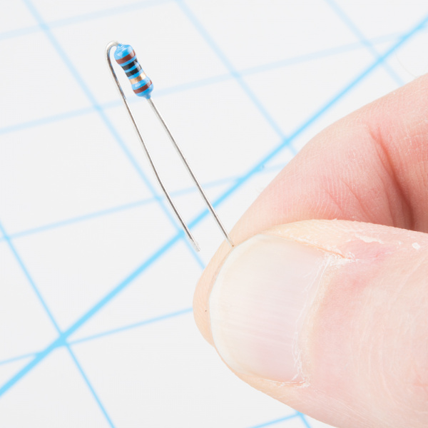
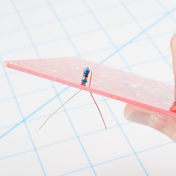
To fit the resistor to the board, bend one lead sharply at the end of the body, doubling back 180°, so the overall result looks like a hairpin.
Then insert the resistor into the board, and splay the leads so they hold it in place while you solder.
After soldering each resistor, trim the leads close to the solder fillet.
There are nine pieces of each of five different resistance values in the kit. Each value will be installed adjacent to each rotary switch. Each row is labeled with the value to be installed there.
If you're unsure about reading the stripes on the resistors, you can use a multimeter to verify their value.
Soldering Rotary Switches
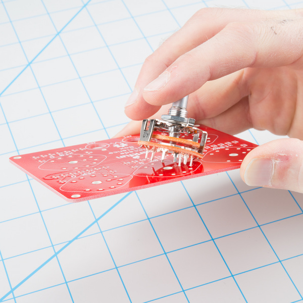
After the resistors are in place, install the rotary switches. The rotary switches fit within the matching outlines on the board. The footprint is slightly asymmetrical, so they only fit the PCB in one orientation.
The five switches are all the same, and interchangable on the PCB. Insert them into the footprint, and solder all eleven leads in place. If you're going to put the decade box in an enclosure, ensure that the switches sit flat on the surface of the board before soldering.
Finally, the center pin of each rotary is longer than the others. You can snip this off with cutters after soldering.
Binding Posts
If you're installing the decade resistance in an enclosure, skip ahead to the next section. You'll mount the jacks to the enclosure, rather than the PCB!
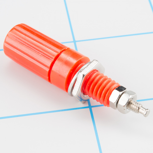
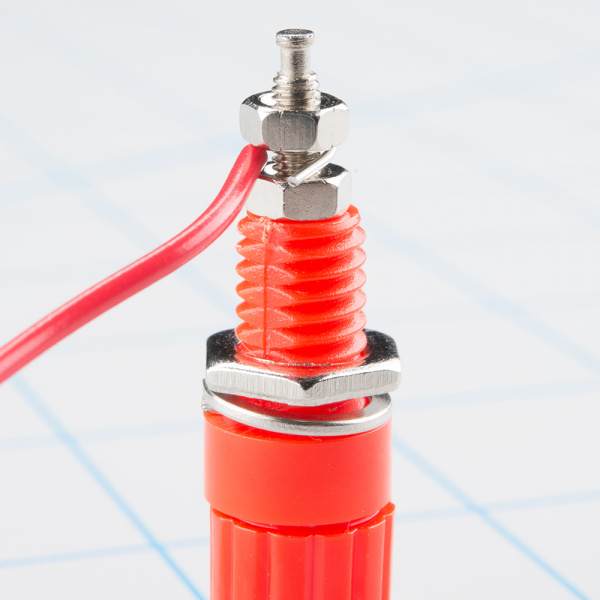
Before we install them, let's take a moment to look at how the banana jacks go together. The back side of the jack is threaded, with a large nut that holds the jack in place. However, this only provides the mechanical mounting of the jack. If you look closely, there are a pair of smaller nuts on the tail of the jack. The outer of these nuts is for electrical connection, and the inner nut holds the jack together. To use the jack, we first need to make sure that the inner nut is snug against the body so the jack doesn't come apart. We'll then use both the mounting and electrical connections.
Even though there are red and black jacks, the decade box has no specific polarity - it doesn't matter which one is mounted in which hole. The color coding is just a convention that can be useful to trace connections on a busy workbench.
First, remove the larger nut from the jack, then insert the jack through the PCB, and reinstall the nut. Take care to not over-tighten, or you can strip the plastic threads.
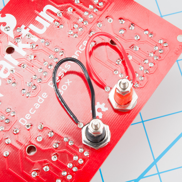
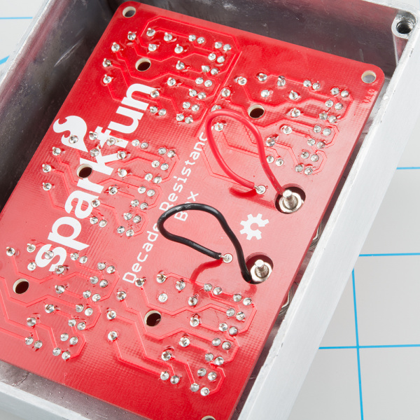
Once the jack is securely mounted, take a 2 inch piece of solid-core wire, and strip the ends. Bend one end into a question-mark shaped curl.
Loop the curl around the metal end of the binding post, and tighten the small nut to hold it in place. This is much easier to do if the curl points in the clockwise direction. Otherwise, tightening the nut will cause the wire to uncurl and come off the post.
With the wire secured to the post, solder the other end of the wire to the nearby PCB pad.
With the first jack mounted, repeat this for the other jack.
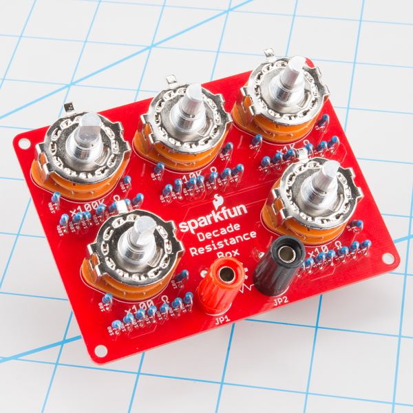
With all of this complete, your decade box should look like this
Installation In Enclosure
If you have opted to put your kit in an enclosure, the assembly changes a bit.
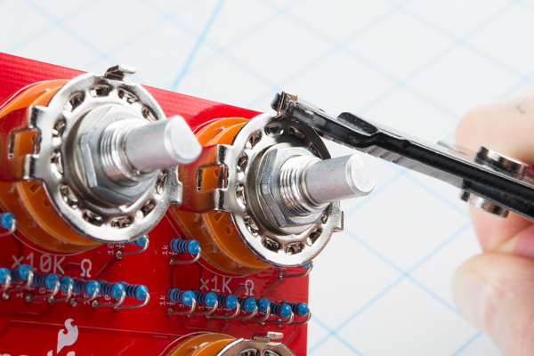
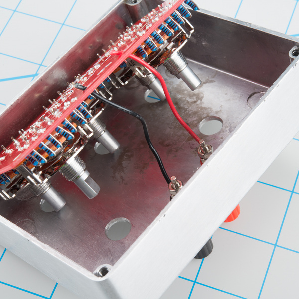
First, the rotary switches have an alignment tab that sticks up, and prevents them from mounting flush behind the panel. With a small pair of pliers, simply bend the tab so the switch body lies against the backside of the panel.
The binding posts are also mounted somewhat differently. Secure them to the panel of the enclosure, rather than the PCB.
Then install the wires on the back of the binding posts. Run the wires through the oblong holes in the PCB, and solder them in place.
Carefully pull the wire slack through the holes, as you slide the PCB into the enclosure. The rotary switches will protrude through the corresponding holes in the enclosure, and the tails of the binding posts will barely stick through the oval holes in the PCB.
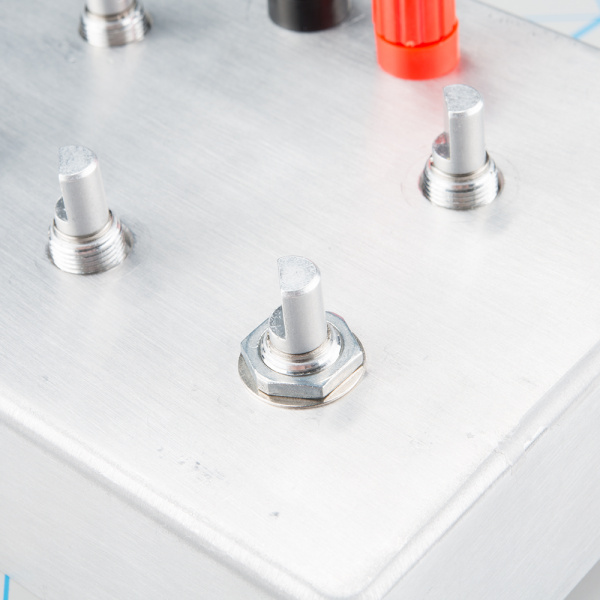
Secure the PCB in the box by mounting each rotary switch with the dress washer and hex nut. You can use pliers or a 12mm socket to tighten the nut.
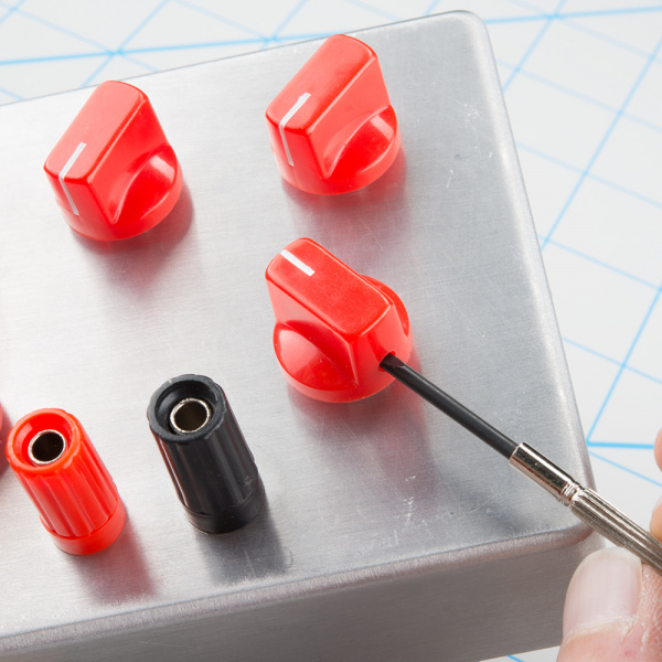
Finally, put the back on the enclosure, and attach the knobs. If you're using the knobs recommended above, the set screw will tighten against the flat side of the shaft, 180° opposite the indicator.
Quick Test
With the assembly complete, you can give the decade resistance a quick test with a multimeter. Select the resistance scale on the meter, and measure between the binding posts.
With five switches that can each take ten positions, there are 100,000 combinations! We couldn't call this section a "quick test" if we were going to try to hit all possible settings, so we'll use a streamlined approach instead. We'll verify that every switch and every resistor is properly installed and functional. If they're right in isolation, we can extrapolate that they'll be right in combination.
- Start with all of the rotary switches at zero. You should measure close to zero ohms on the meter.
- Select the 10's position switch, and click it through each of it's steps. The meter should read an additional ten ohms for each click of the switch.
- After you have measured the top position (90 Ω), reset the switch to zero.
- Repeat the above steps for each of the other rotary switches.
A Note On Accuracy
It's worth mentioning that the meter readings in the above test will not absolutely match the settings on the decade box. For instance, the 90 Ω setting might read as 89.3 or 90.5 - very close to the ideal value, but not perfect. There are a couple factors that contribute to this.
- First, there is a tiny amount of intrinsic resistance in the circuit. The leads of the multimeter, the traces of the PCB, and other components are not ideal conductors, and exhibit a small amount of "parasitic resistance." In practice, it's small enough to be negligible. If the all zero setting is higher than an Ohm or two, doublecheck your work.
- Second, the resistors in the decade resistance also have a small amount of variability - they're rated to be within +/- 1% of the given value. There are 0.1% tolerance resistors, but they are significantly more expensive than the 1% ones.
- Third, the accuracy and precision of the multimeter itself will show some variance.
How It Works
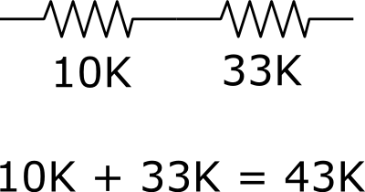
Resistors placed in series are additive. If we connect resistors end-to-end, the overall resistance is the sum of the values. Below, we see that we can make a 43K resistor by adding a 10K to a 33K.
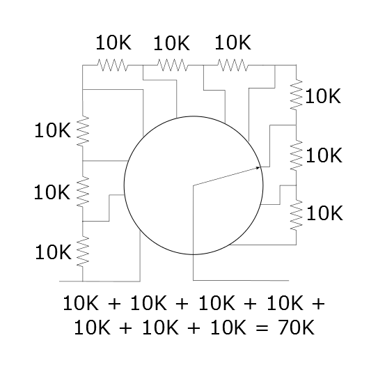
The decade box employs this principle. Each decade is a string of the the same value resistor. A rotary switch is used to select the point in the string that corresponds to the desired value.
Each rotary switch has 10 positions, from 0 to 9. The 0 position simply shorts the switch input to it's output, and each successive position adds one more resistor to the chain. A switch can go between 0 and 9 times the decade value. If we need 10 times or greater the value, we move on to the next decade.
The decades are arranged in series, as well. The tens control feeds the hundreds control, and so on.
Constraints
Before we move on to some example applications of the decade resistance, let's take a closer look at the components, because they place some limits on the decade box.
With modern, low-voltage electronics, we often operate under the assumption that we aren't using much power, or passing much current. Sometimes we are reminded of the power or current involved when things heat up, reset mysteriously, start to smell hot, or catch fire.
To help avoid those situations, let's explore the main constraints of the decade resistance.
Resistors
The first place to look is the resistors. The resistors are rated to dissipate up to 1/4 W each. This might not seem like much, but for many circuits, it's a reasonable upper limit. Let's examine the reasons a little more closely.
We know that power in Watts is calculated using.
P = IV If we don't know the Voltage or Current terms, but we do know the resistance, we can substitute Ohm's law in for the missing I or V term, resulting in
P = (V^2)/R P = (I^2) * R We'll take a shortcut, and assume that the maximum voltage across the decade resistance is the difference between the positive and negative supply rails. For some common supply voltages, we'll calculate the resistance that draws 1/4W.
| Supply Voltage | R that draws 1/4W | Current Through R at 1/4W |
| 3.3V | 43.56 Ω | 75 mA |
| 5V | 100 Ω | 50 mA |
| 9V | 324 Ω | 27 mA |
| 12V | 576 Ω | 20 mA |
| 30V (+/- 15V supply) | 3600 Ω | 8 mA |
This table can serve as a guideline for applying the decade resistance. For a circuit powered by a given voltage, the "R that draws 1/4W" column indicates the resistance below which you need to consider the power drawn by the box.
But this is a guideline, and not a hard rule. Some circuits use high voltage supplies, but don't put the full voltage across the decade box.
Switches
Additionally, the manufacturer states that the rotary switches are limited to passing 300 mA.
To Summarize
If you find yourself dialing in resistances below 500 Ohms, take a moment to work out how much power you'll be dissipating, and current you'll be drawing. The maximum limits for the decade box are overall power dissipation of 1/4 Watt, and the current passed of 300 mA. If you're unsure, you can always use an Ammeter in series with the Decade Resistance to verify the current draw.
If you need help calculating the power dissipation, check out our power tutorial. The multimeter tutorial describes how to measure the current drawn by a circuit.
As a Measurement Tool
Decade boxes can be very useful on an electronics test bench. One traditional application of a decade box is to measure an unknown resistance.
Wheatstone Bridge
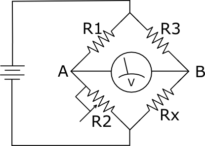
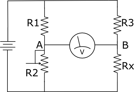
The Wheatstone Bridge is a DC circuit that uses three resistors of known value to measure a fourth resistor (or even other materials, such as soils or liquids). The Wheatstone bridge is commonly drawn as a diamond, as shown below.
Notice that there is a battery (or other DC source) on the left, powering the top and bottom of the diamond. At the center of the diamond, between points A and B, is a voltmeter.
The diamond drawing obscures what's really happening in the circuit. If we rearrange and redraw the circuit, we recognize that it's a pair of resistive voltage dividers.
The voltage at point A is determined by the ratio of R1 and the variable resistance R2, while the voltage at point B is determined by the ratio of R3 and the unknown Rx. If the two ratios are the same, the A and B will have the same voltage, and we can infer the value of Rx.
R2/R1 = Rx/R3
Which we can solve for Rx:
R3(R2/R1) = Rx
And if R1 is equal to R3, it simplifies to
R2 = Rx
If R2 is a decade box, we can simply read it's value, and we'll know the value of the unknown resistor!
Wheatstone Bridge In Action
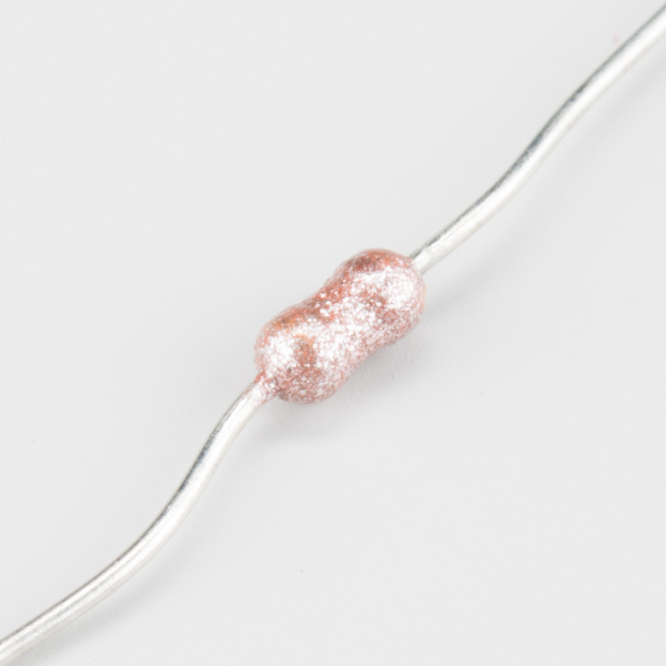
To test my Wheatstone bridge, I had one of my colleagues pull a random resistor from my spare parts box, and paint it over, so I couldn't read the stripes.
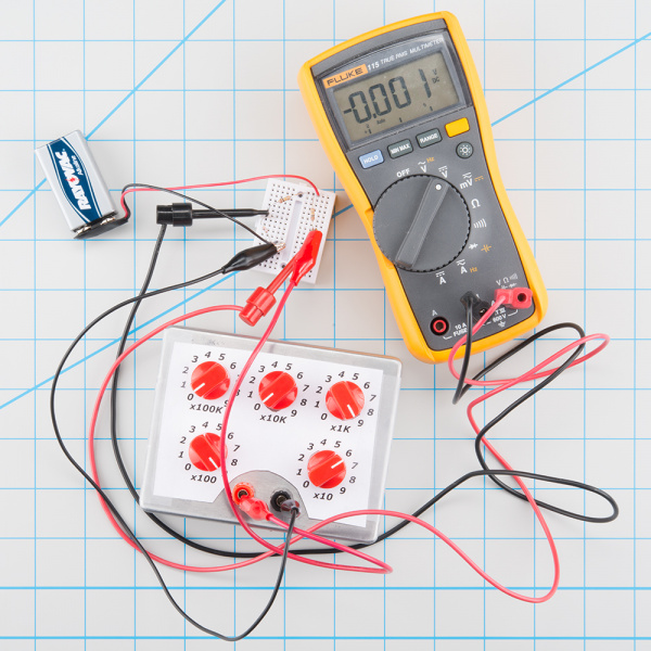
I built a Wheatstone bridge using a 9V battery, and 100K resistors for R1 and R3. The unknown resistor was inserted as Rx, and a decade box was inserted as R2. A digital voltmeter was inserted between points A and B, the centers of the dividers.
The value of the decade box was adjusted until the voltage displayed on the meter was as close to 0V as could be reached. In this case, the meter was flickering between 0.000 and -0.001. At that point, the value of the decade box matched the value of the unknown resistor. As you can see, we measured 9,960 Ω. The mystery resistor was probably a 10K Ω, +/- 5% tolerance resistor.
In practical terms, it would have been easier to just use the digital multimeter to read the resistor directly, but Wheatstone bridges have uses in certain types of instrumentation - they can be configured to observe very small changes in resistance, such as the output of a strain gauge. They're also known to torment engineering students in circuit class laboratories!
Experimental Circuit
Since portable digital instruments have mostly superseded traditional techniques like the Wheatstone bridge, lets explore a more practical application on the designer's workbench.
Variable Gain Amplifier
Sometimes, when we're interfacing an analog signal with a microcontroller, the analog voltage doesn't match the range of the analog-to-digital converter. For instance, the signal might swing 100 mV, but the converter is referenced to 5V - the converter would only use 2% of it's range.
To match the signal to the converter, we can build an amplifier circuit that boosts the incoming voltage. This circuit is known as a "conditioning amplifier" or "pre-amplifier" ("preamp" for short).
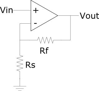
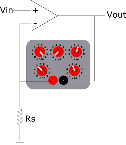
One simple preamp is an operational amplifier wired in non-inverting mode. The gain of the amplifier is configured with a pair of resistors.
The gain factor for the amplifier is
1+(Rf/Rs) For a given pair or resistors, we can calculate the gain factor - for example, if both are 10K Ω, the equation works out to
1+(10,000/10,000) Which simplifies to 2 - the output of the amplifier will be the input voltage multiplied by 2. To continue the example above, if 100mV go in, then 200 mV come out.
Sometimes when we start designing, we don't know the gain factor we need for an application. When building an amplifier to suit a specific application, it can be useful to have a preamp with adjustable gain. We can build one that uses a decade box for the feedback resistor, and selecting a shunt resistor that gives us a reasonable gain range.
With a decade box that goes to 999,990 Ω, and a 4.7K Ω resistor for the shunt, we can get a wide range of amplification, as shown in the following table.
| Arithmetic Gain | R1 (Shunt) | R2 (Feedback) |
| 1 | 4700 Ω | 0 |
| 1.212 | 4700 Ω | 1000 |
| 3.12 | 4700 Ω | 10,000 |
| 22.2 | 4700 Ω | 100,000 |
| 213 | 4700 Ω | 999,999 |
Once we have found the right resistor combination, we can remove the decade box, replacing it with a single resistor.
One thing to note with the non-inverting amplifier is that it can only increase the input, not reduce it (there's no way to select resistors that get rid of the 1 in the equation). The inverting amplifier also uses two resistors to configure gain, but can be configured for fractional (less than 1) gain, though this comes at the cost of other complexity. As the name states, this configuration inverts the signal at it's output - a situation that can be solved in software, but is also somewhat counter-intuitive.
Resources and Going Further
Decade boxes are handy to have on your workbench - you never know when you'll need to dial in a resistance. For more information about the decade resistance box, check out the resources below:
Here are some accessories that you may want to have around when using with the decade resistance box.
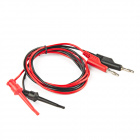
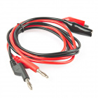
- Banana to IC Hook or Banana to alligator leads are useful for connecting the decade resistance to other circuits.
- Building a non-inverting amplifier? You'll need some operational amplifiers.
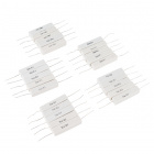
- If you need small resistances that can dissipate more power, check out our Power Resistor Kit, rated to 10W each.
Op-Amp (Through-Hole) - LM358
COM-09456Need some inspiration? Check out some of these related tutorials:
- Theory behind the Wheatstone Bridge.
- Moving beyond the Wheatstone bridge, the Wein Bridge uses similar nulling techniques to measure capacitors, and a Maxwell Bridge measures inductors.
- An interesting anecdote from Howard Johnson regarding where precision resistors come from.
