DeadOn RTC Breakout Hookup Guide
 jimblom
Hardware Overview
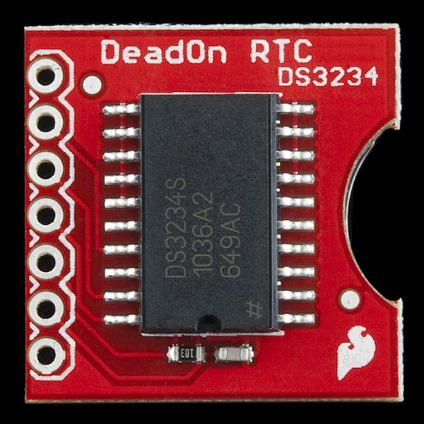
The DeadOn RTC Breakout surrounds the DS3234 with all of the components it needs to count time, communicate, and maintain power. The communication and power pins are all broken out to a single, 7-pin header. The top side of the board houses the IC itself and a couple passives to support it:
While the bottom side of the breakout labels the pins and mounts the 12mm coin cell battery holder:
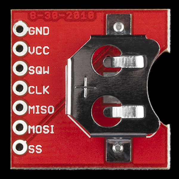
Pinout
The seven pin breakouts on the board provide access to the communication interface, power supply, and the square-wave/interrupt output of the DS3234:
| Pin Label | Input/Output | Description |
|---|---|---|
| GND | Supply Input | Ground (0V) supply |
| VCC | Supply Input | DS3234 VCC power supply input |
| SQW | Output | Configurable square-wave output Alarm 1 and/or Alarm 2 interrupt output |
| CLK | Input | SPI clock input |
| MISO | Output | SPI master in, slave out |
| MOSI | Input | SPI master out, slave in |
| SS | Input | SPI active-low chip select |
CLK, MISO, MOSI, and SS make up the DS3234's SPI interface. All four need to be connected to your microcontroller's I/O pins to allow communication between the chips. Use of the multi-talented SQW pin is optional, but it can come in very handy if you're using alarms or need an extra time-keeping output. More on that and the power supply pins below.
Powering the DS3234
The Deadon RTC breakout board does not include any voltage regulation, so power supplied to the "VCC" pin should be kept within the DS3234's (wide) recommended operating range: 2.0 to 5.5V. Fortunately, the breakout should work with either 3.3V or 5V development boards!
The chip is designed to be as low-power as possible. While its powered at 5V, during communication bursts, the chip may consume upward of 400-700µA, but it will usually run closer to 120µA. When the primary power supply is removed and the chip is running off its backup battery, it will consume around 2µA.
Assuming it has capacity of 47mAh, a fully charged 12mm coin cell battery can keep the DS3234 running for up to 2.68 years, if the chip consumes an average 2µA!
(47mAh / 2µA = 23500 hours = 979.17 days = 2.68 years)
Alarms and the SQW (Square Wave)/ Alarm Interrupt Output Pin
One of the DS3234's most unique features is its pair of configurable alarms: appropriately named "Alarm 1" and "Alarm 2." The higher-resolution alarm 1, can be set to trigger on any second, minute, hour, and/or day/date combination, while alarm 2 can monitor anything from minutes to days/dates. With every second that passes, the DS3234 compares the time with any alarms that may be set. If everything matches, the chip sets a flag to indicate that one, or both, of the alarms has triggered.
Aside from its SPI pins, the DS3234 also features a very versatile pin, labeled "SQW." This pin can be configured as either a square wave output (with output frequencies ranging from 1Hz to 8.192kHz), or as an active-low interrupt output, indicating an alarm has been triggered.
In order to use the SQW pin as an output or interrupt, it must be connected to a pull-up resistor. A 10kΩ resistor, connected between SQW and VCC, or your microcontroller's internal pull-up resistors should do the job.