DeadOn RTC Breakout Hookup Guide
 jimblom
Hardware Hookup
Before you can insert the DeadOn RTC Breakout into a breadboard, or otherwise connect it to your microcontroller, you'll need to solder something to the 7-pin header. If you plan on breadboarding with the chip, we recommend straight male headers. Female headers or even a few strips of wire are other good options.
If you're soldering headers, you may want to insert the pins into the "top" side of the board -- maintaining access to the battery and a good view of the labels.
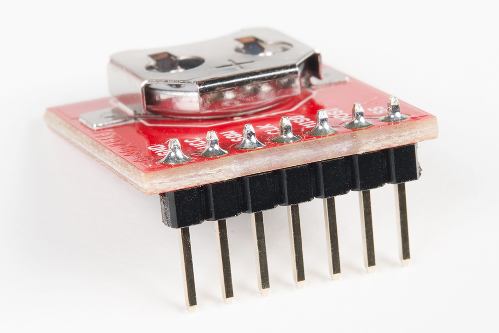
Conveniently, the header's shroud is about the same height as the DS3234, so it shouldn't interfere with breadboard-plugging.
Inserting the Battery
The DeadOn RTC Breakout does not ship with a 12mm coin cell, but the battery is recommended -- without it, the RTC will lose track of time whenever power is lost. When inserting the battery, make sure the "+" sign is facing up -- it should touch the top of the battery holder.
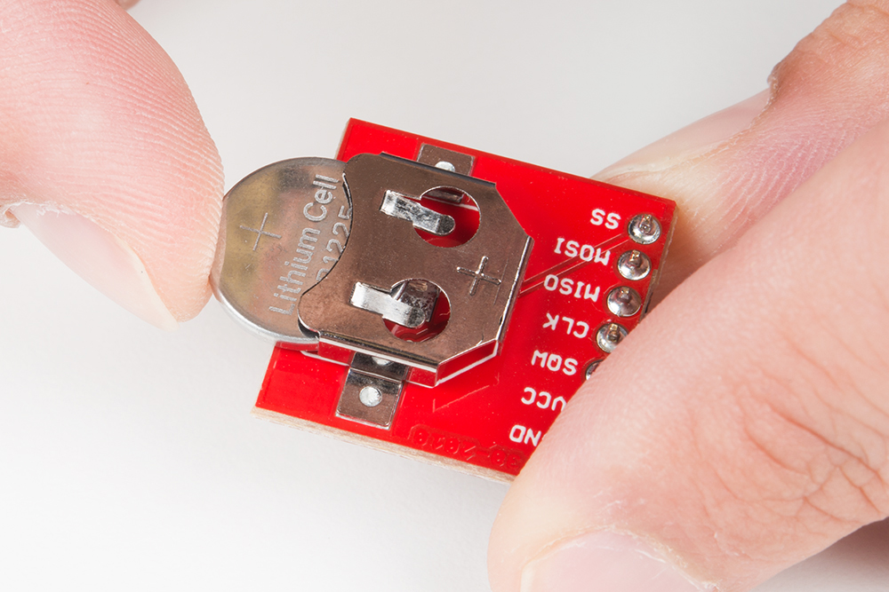
Hopefully you won't have to remove and replace that battery for a good many years!
Example Circuit
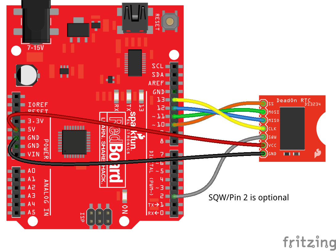
The DS3234's SPI interface means, to interface with the chip, you'll need at least six wires between your microcontroller and the breakout board: power, ground, master-in/slave-out (MOSI), master-out/slave-in (MISO), serial clock (SCLK), and slave-select (SS).
Here is an example hookup diagram demonstrating how to hook the board up to an Arduino Uno. The diagram also connects SQW to the Arduino, using the pin as an interrupt output. This wire is optional, but you'll have to (very slightly) modify the example code if it's not connected.