Copernicus II Hookup Guide
Contributors:
 Toni_K
Toni_K 
Hardware Hookup
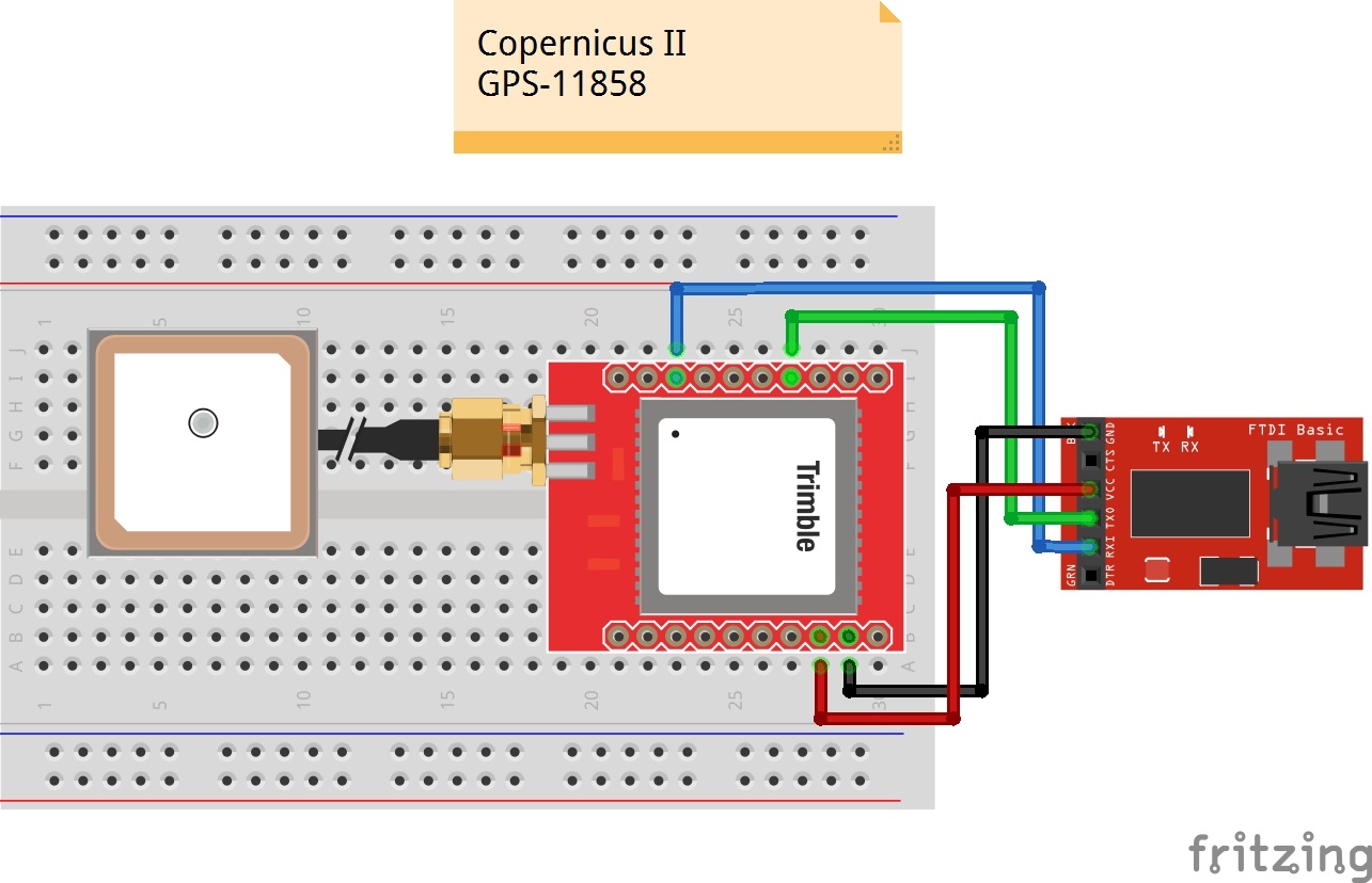
To get started communicating with the Copernicus II, you will need to connect four pins on the module: VCC, GND, TX-B, and RX-B.
For our example, we will be connecting the module to a terminal window on the computer using an 3.3V FTDI Basic Board, and will be using the GPS Antenna Embedded SMA.
Connections:
Copernicus II → 3.3V FTDI Basic
- VCC → 3.3V
- GND → GND
- TX-B → RXI
- RX-B → TXO
Take a look at the Fritzing diagram below showing the connections between the Copernicus II and the FTDI Basic based on the pin descriptions from the datasheet. In some cases, users needed to connect R2 to Vcc to operate but it should not be necessary.
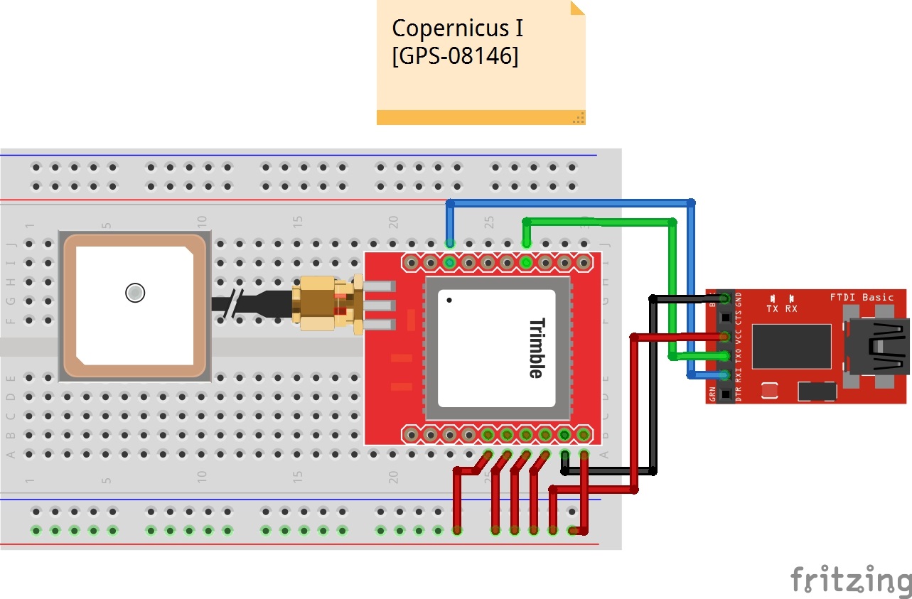
Heads up! If you have the old Copernicus I, the pinout and hookup is different. You old SKU for the part is GPS-8146 and can be distinguished with a "58052-00" printed on the IC. The Copernicus II should have "68340-00" printed on the IC.Check out the old datasheet on page 23 for the Copernicus I for more information. Users reported needing to connect XRST, BOOT, R2 and XSTANDY to VCC in order for the module to operate.