Continuous Rotation Servo Trigger Hookup Guide
 Byron J.
Theory Of Operations
The Servo Trigger consists of two major engineering deliverables, the hardware design, and the firmware. The hardware is actually the same for the regular and continuous rotation boards, but they're loaded with different firmware, tailoring the board's behavior to each type of servo motor. Both sets of deliverables are in the Servo Trigger Github repository.
On The Board
Let's look at the components on the board and examine what they do.
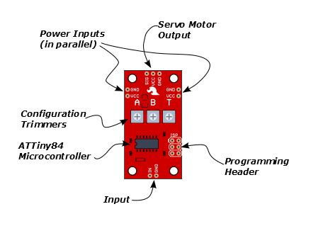
The heart of the Servo Trigger is an Atmel ATTiny84 microcontroller, running a small program that implements the servo control features we are discussing here. Just because the Servo Trigger saves you from needing to write code doesn't mean that there was no programming involved!
The servo control signal is generated using a 16-bit hardware timer. It runs off a 1 MHz clock, counting to 20000 to generate the 20 mSec (50 Hz) period and is configured to generate pulses that range from 1000 to 2000 µSec (1 to 2 milliseconds).
The three potentiometers are connected as voltage dividers between VCC and ground. They are read using analog inputs ADC0, ADC3, and ADC7.
The switch input is read using PortA, input pin 1. It is debounced in software and can be configured to watch for a switch closure or a logic level pulse.
The board also includes the common 6-pin in-system-programming header, which we'll discuss in the Servo Trigger Programming Guide. But we're getting a bit ahead of ourselves -- there are some configuration options you can use without programming.
Configuration
The Servo Trigger has a couple of configuration options. If you look at the back of the PCB, you'll notice two solder jumpers that can be used to change Servo Trigger's response.
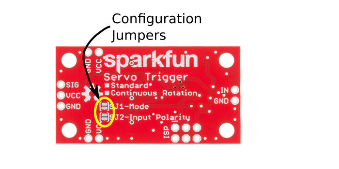
When it first powers up, the servo trigger reads these jumpers and configures itself accordingly.
Modes
The Servo Trigger has two different servo control modes, selected with solder jumper 1 (SJ1). They can be used to tailor the response of the board for different applications.
The default mode implements toggling control. The trigger initializes driving the servo as instructed by trimmer A. When the switch closes, it transitions to the speed indicated by B. When the switch closes again, it returns to A. The time taken to get between A and B is selected using trimmer T, which ranges from nearly instantaneous to 10 seconds, allowwing the motor to gradually slow, stop, and reverse.

This behavior can be changed by flowing solder between the pads of the mode jumper.

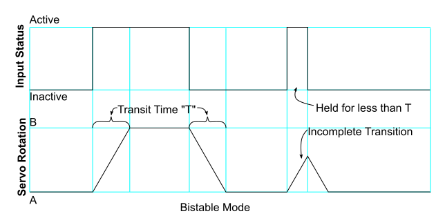
With the solder jumper closed, the mode changes to bistable control -- the servo will drive at speed A while the switch is open, and speed B while the switch is closed. While the switch input stays in a state, the servo drives at the corresponding speed -- it is stable in two different states.
Input Polarity
The Servo Trigger input sensitivity can also be changed, using solder jumper 2 (SJ2).
The default configuration, with no solder applied, configures the Servo Trigger for use with a normally-open switch, with the internal pull-up resistor on the microcontroller enabled. This configuration is also suitable for use with an active-low logic input.
With SJ2 closed, the internal pull-up is disabled, and the input is set as an active-high logic input.
A note about nomenclature: since the input polarity can be swapped, it can be hard to talk about -- the voltage might be high, but when the sense is inverted, it indicates that the input isn't being actuated. To help navigate this, the polarity-neutral terms active or asserted are used to describe when the input is being used, and inactive or deasserted to describe the default state.
More components
The servo trigger can be used with a wider variety of external components than used in the example above. We used a standard size continuous rotation servo, though we also offer a micro size one.
You can also use different switches, such as micro switches or foot pedals.
Power Notes
Compared to a servo motor, the Servo Trigger board draws very little current -- roughly 5 mA.
The motor draws significantly more -- a quick bench test using a small servo, with only a lightwieght horn attached, shows the motor draws 10 mA sitting idle, and about 70 mA while moving. Grabbing the horn and twisting causes the controller to apply current to the motor, counteracting the twist. It drew 700 mA during this test -- a larger servo could draw even more!
These currents can get surprisingly high as you add more motors to the system -- you'll need to select a power supply with adequate capacity. An Ampere per motor is a reasonable guideline. For more information about powering servos, please see the powering a servo section of our Servo Tutorial.
When in doubt, grab a multimeter, measure the current consumed, and check whether VCC at the board input is falling below the expected voltage when the servos are turning.
Troubleshooting
If there's no change when you actuate the input, first check that A and B are not set to the same position, otherwise there's no speed change!
If you're feeding the input with a logic signal from an external device, be sure to drive the signal for more than 50 milliseconds. The PWM signal is updated every 50 mSec, and events shorter than that may be missed.
If the servo only turns on one direction, doublecheck that the trimpot on the servo is near the center of its range. If it's near one end or the other, the servo will go from full speed to stopped, but not reverse.
For additional servo troubleshooting ideas, please consult the Servo Turorial.