Continuous Rotation Servo Trigger Hookup Guide
 Byron J.
 Example Project
To demonstrate the usefulness of the Continuous Rotation Servo Trigger, we put a continuous rotation servo on a small camera dolly. The dolly has a whisker switch at each end, allowing it to do automated tabletop camera moves.
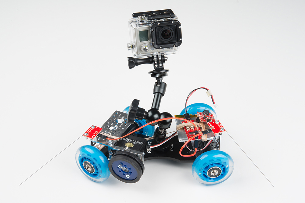
Lacking an old-fashioned rollerskate to dismantle for the chassis, we started with a commercial camera skate dolly.

We also had some derelict robot parts around the workshop that we used to hold everything together. We improvised using materials we had handy and suggest that you do the same!
Build the Circuit
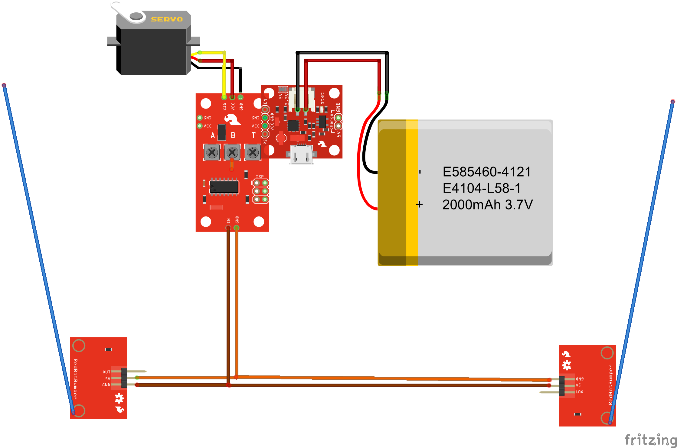
To start, we assembled the circuit on the workbench.
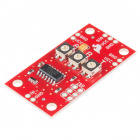
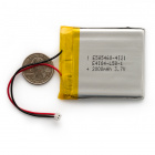
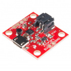
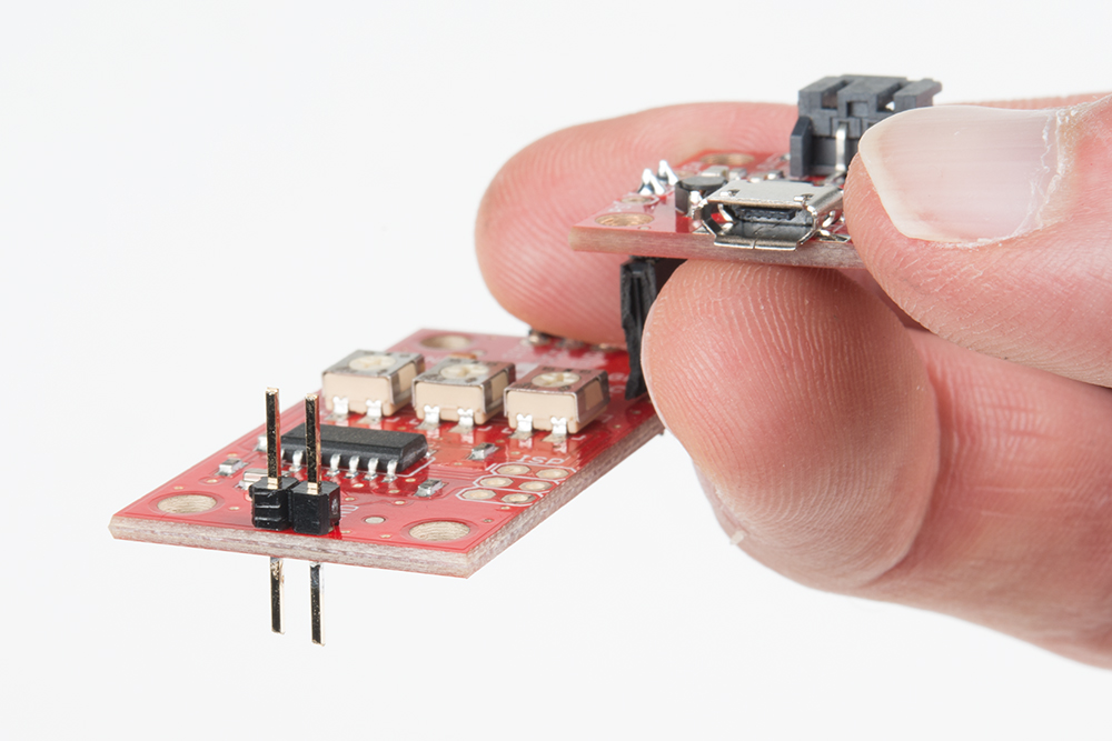
We used male and female headers to stack the Power Cell atop the Servo Trigger board.
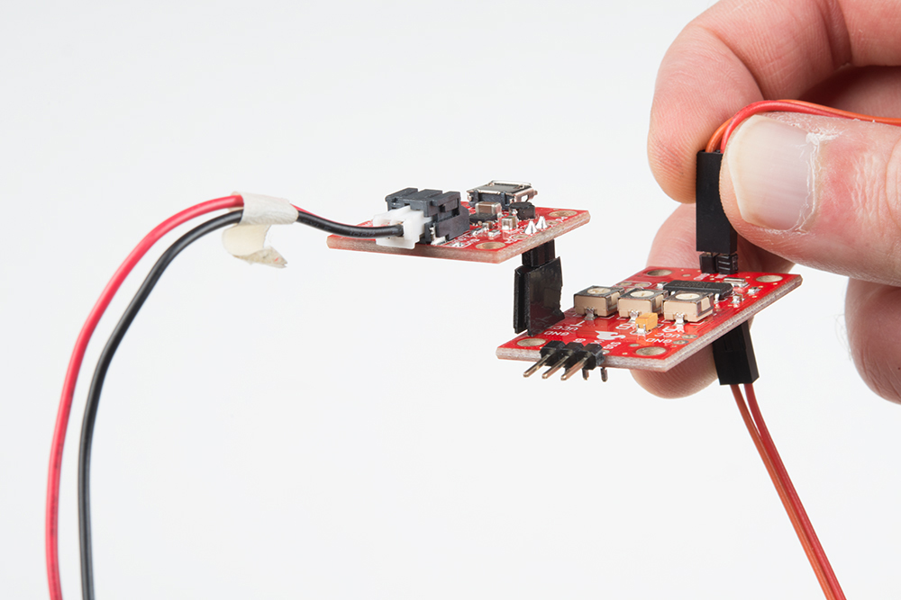
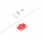
The whisker switches were assembled as described in this hookup guide, with one built in right-hand orientation and the other left-handed.
The whisker switches also needed a quick electronic modification to make them compatible with the Servo Trigger. We desoldered the resistor from the PCB and replaced it with a blob of solder, so the whisker acts as a simple switch closure.

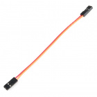
We plugged the 2 pin jumper wires into the GND and 5V pins on the switches and stuck some long pin headers through the switch contacts on the trigger PCB, so the switches could both plug in in parallel, one from above, the other from beneath.
We gave it a quick test on the bench. Each time a whicker switch closed, the motor drove the other way. The A, B, and T adjustments each had the desired effect.
Mechanical Integration
With the electronics working, we put them on the chassis.
The chassis itself consists of a platform with a couple of protruding M6 machine screws. The axles are mounted to the screws with wingnuts.
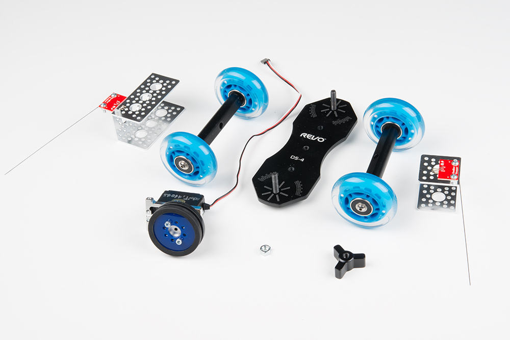
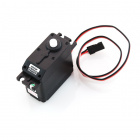
The drive mechanism for the cart is a simple slip clutch. We fashioned a double-width rubber wheel onto the servo using Actobotics 2" wheels and a pair of servo hubs. The motor was mounted to a B-type servo bracket, which was connected to the end of a 4.5" channel. The bracket was free to pivot in the end of the channel.
The bracket channel was simply placed over the axle bolt on the cart chassis. A rubber band was looped around the assembly, putting tension on the servo, so that the drive wheel gently touched one of the skate wheels.
On the other end of the cart, a 1.5" channel was placed over the other pivot. This allowed both axles on the cart to be spaced evenly, ensuring that all four skate wheels touch the tabletop. It also gave us some holes to mount the front whisker switch and a place to secure the battery and other electronics.
Testing Results
The first time out was somewhat disappointing -- the cart would drive until the first switch closed, then stall. It turns out the battery was nearly discharged! After a couple hours charging from a USB port, it behaved as expected.
We adjusted the trimmers so it drove slowly in both directions, with a medium transition time, so it wouldn't skid or jerk as it turned around.