Continuous Rotation Servo Trigger Hookup Guide
 Byron J.
 Getting Started Quickly
Let's jump in and build a circuit to show how the Servo Trigger works!
Materials and Tools
You'll need to following materials to build this example circuit found in this tutorial.

You'll also need some hookup wire and a small screwdriver.
Doublecheck The Trigger
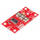
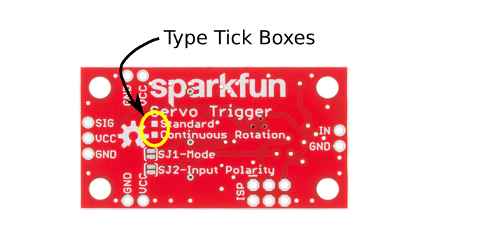
Before we start building, doublecheck that you've got a Continuous Rotation Servo Trigger. There are tick boxes on the back of the PCB, and the "continuous rotation" box should be marked.
Preparations
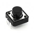
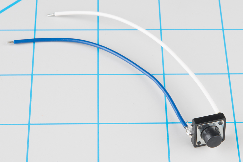
To start, solder some wires to the tactile switch. If you solder to legs on on opposite corners (top-right and lower-left, for instance), you can be confident that you'll get a contact closure when you press the button.
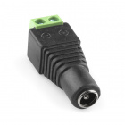
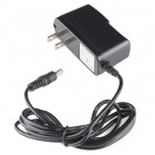
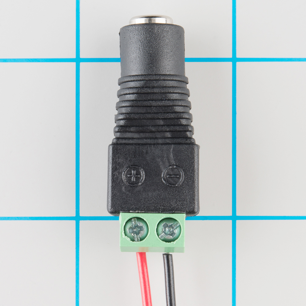
Next, prepare the power plug pigtail. Take a pair of wires, and strip the ends. Then screw them to the power jack adapter -- if you look closely at the adaptor, you'll notice that there are a small + and - embossed in the plastic. We used a red wire for VCC on the + terminal and a black wire for ground on the - terminal.
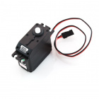
Take your right-angle male headers, and snap of a section of three headers. Solder the 3-pin header to the three pads on the end the board, and plug the servo into the the header. Be careful to get the plug oriented correctly -- you can check the color code table in the servo tutorial, or consult the servo manufacturer's datasheet.
Solder the switch wires to the IN and GND pads on the Servo Trigger and the power pigtail to the VCC and GND pads on the edge of the board. These are mirrored on opposite edges of the board -- they're wired in parallel, so you can use either set of pads. The red wire should connect to the VCC pad and the black to GND.
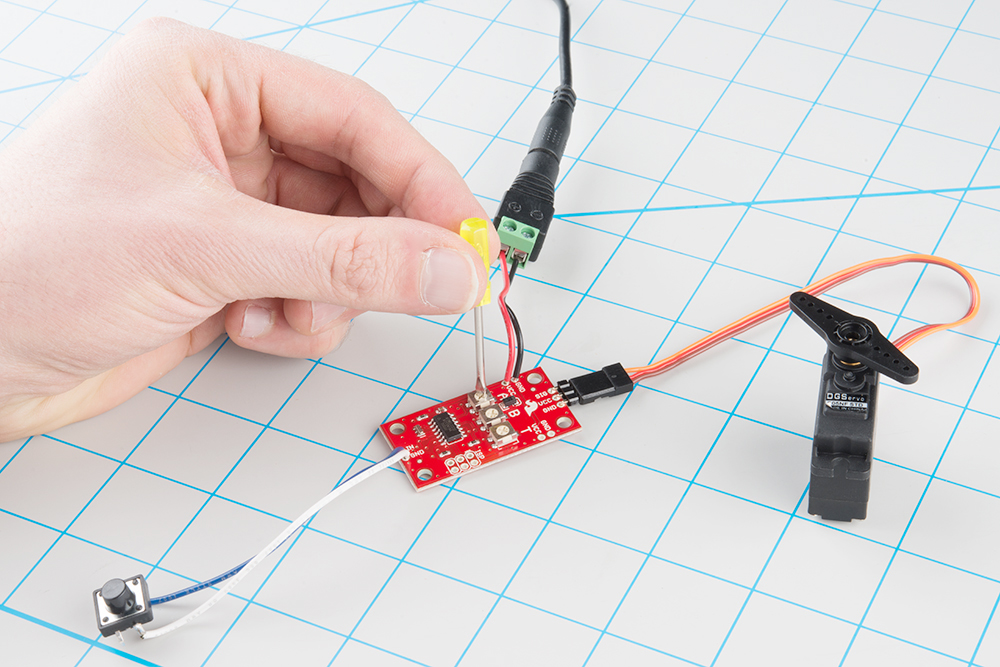
Before we power up, take a moment to double-check your work against the photo below (click on the picture for a larger version). In particular, make sure that the power and servo connections are oriented correctly.
Adjust the trimpots on the back of the board. Set A fully counterclockwise, B fully clockwise, and set T to the middle.
Finally, apply power. The servo should start to turn. If not, power down, and recheck your work.
While it's running, tap the switch. The servo will take a couple of seconds to slow down, stop, then reverse. Tap the switch again, and it will go back to the original direction.
Now you can adjust the trimpots to configure the servo.
Asets the speed and direction of the motor before the switch is actuated.Bsets the speed and direction of the motor after the switch is actuated.Tsets the time it takes to get from A to B and back.
When A and B are near the middle of their rotation, the servo will stop. Turning them clockwise from there instructs the servo to turn in one direction; turning them counterclockwise results in the opposite direction. The farther from the center, the faster the servo turns. The transition time is adjustable between 50 milliseconds and 10 seconds. The transition time is constant -- when set to 2 seconds, the servo will take 2 seconds to move between A and B, regardless of how close the A and B settings are.
In the next section, we'll explore some of the finer details of the Continuous Rotation Servo Trigger.