Connector Basics
Pin Header Connectors
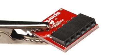
Pin header connectors comprise several different means of connection. Generally, one side is a series of pins which are soldered to a PCB, and they can either be at a right-angle to the PCB surface (usually called "straight") or parallel to the board's surface (confusingly referred to as "right-angle" pins). Such connectors come in a variety of pitches, and may have any number of individual rows of pins.
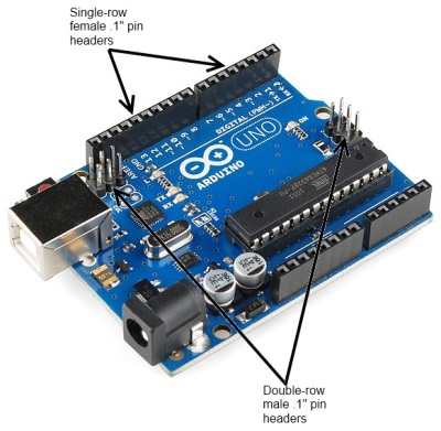
The most commonly seen pin headers are 0.1" (2.54mm) single or double row connectors. This is a standard breadboard compatible pitch. These come in male and female versions, and are the connectors used to connect Arduino boards and shields together. Users can easily connect jumper wires to breadboards.
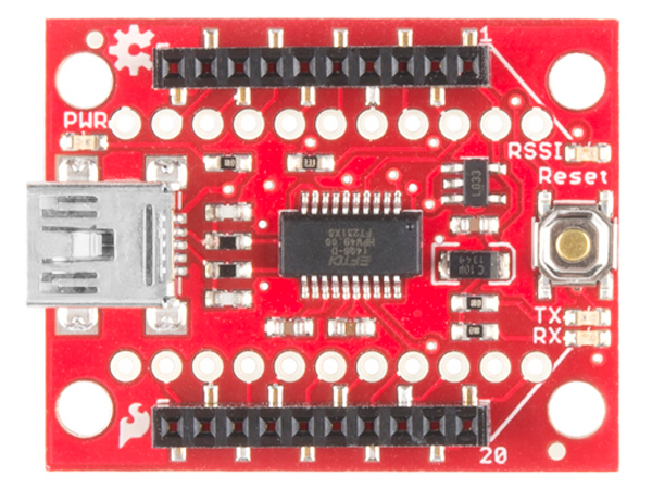
Other pitches are not uncommon; for instance, the XBee wireless module uses a 2.0mm pitch version of the same connector. Below is a top view showing the SMD 2.00mm pitched female header soldered on the board. As you can see, the two rows of plated through holes for standard breadboard compatible headers next to the headers are spaced at 0.1" (2.54mm) apart.
A common variation on this part is a "machine pin" version. While the normal version is formed out of stamped and folded sheet metal, machine pin connectors are formed by tooling the metal into the desired shape. The result is a more robust connector, with a better joint and longer life, making it somewhat more expensive.
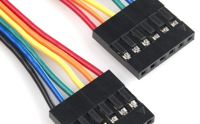
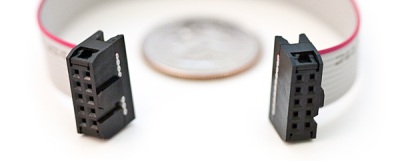
Cables made to connect to these pin headers are usually one of two types: individual wires with crimp connectors on them or ribbon cables with insulation displacement connectors. These can simply be clamped onto the end of a ribbon cable, which creates a connection to each one of the conductors in the ribbon cable. Generally, cables are only available as female gender and expect a male pin to mate with.
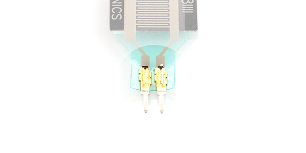
Flexible circuits can also use solder tabs spaced with the standard 0.1" pitch. These tabs are stapled through a flexible substrate in order to make contact with the semi-conductive material.
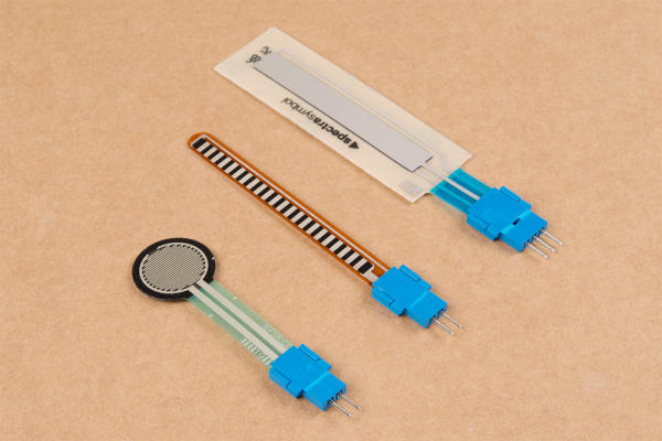
Depending on your project application and skill set, there are a few methods of connecting to the solder tabs. Users can insert the solder tabs into breadboards or solder directly to the pins However, the thin solder tabs can break over time when bent excessively and can become loose in a breadboard socket. Flexible sensors can also be sensitive to heat due to the semi-conductive material. As an alternative, the Amphenol FCI Clincher connectors were designed with thicker leads and breadboard compatible sockets for a more reliable connection.
