Cherry MX Switch Breakout Hookup Guide
 jimblom
Matrixing Breakouts
The Cherry MX Switch Breakout Board's are designed with switch matrix-ing in mind. By creating a row/column matrix of switches, you can save on potentially dozens of microcontroller I/O pins. A 64-key keyboard, for example, can be scanned with just 16 I/O pins.
Key Spacing
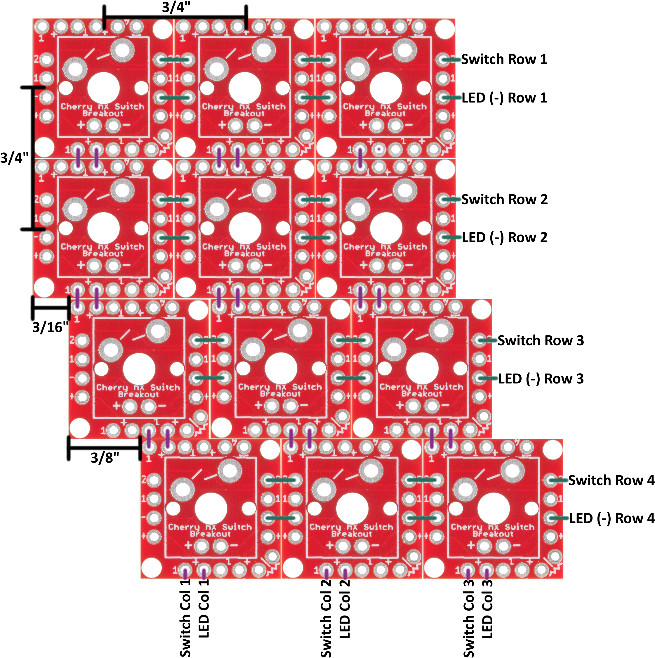
While there is no specific standard for keyboard key spacing, most full-size keyboard keys are spaced by 3/4" (0.75in) from center-to-center. Rows may be offset by either 3/8" (0.375in) or 3/16" (0.1875in), or not at all.

The breakout is designed to make typical key spacing as easy as possible. By cleverly jumping one board to the next, you can add any of the standard offsets to nearby rows.
So, plan out your keyboard, and grab a soldering iron!
Creating a Key Matrix
To create a matrix of switches, arrange your boards as desired. Along the rows, line up the "2", "1", "-", and "+" labels. You will, however, only connect the "2" and "-" pins across rows. Solder your rows together first:
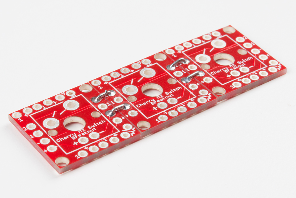
There’s not an easy method to soldering boards together. You’ll probably need wire strippers to split and cut solid-core wire into tiny (~3/8") pieces. A third hand can be a big-time help keeping boards stationary while you solder the little wires in place.
Once you've created your rows, line up the columns by matching the "1" and "+" pins. There are three offset options available, as documented in the image above.
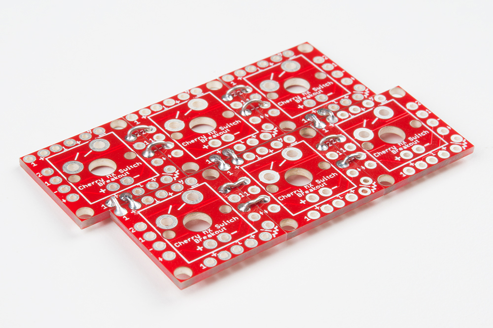
Here is an example of a fully built-up 3x3 matrix. The middle row is offset from the top by 3/16", and the bottom row is offset from the middle by 3/8". This will make the middle row equivalent to a keyboard's A, S, and D keys, the top row Q, W, and E, and the bottom row Z, X, and C -- we're making a 9-key keypad centered around WASD!

Finish off the soldering job by connecting wires to the row and column pins you'll need access to. If you're not using any LEDs, you'll only need to solder to the "1" pins along the rows, and "2" pins along the columns.
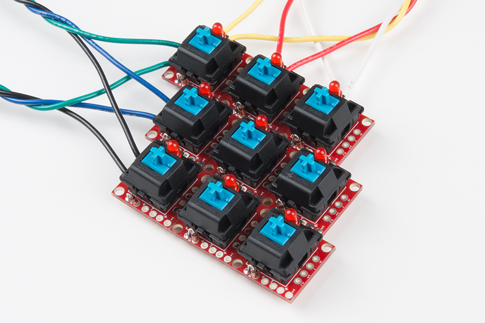
Don't forget to add your switches, and LEDs, resistors, or diodes, should your project require them!
Keypad Scanning Arduino Code
Here's a simple Arduino sketch, designed to work with a 9-key, 3x3 matrix, but easily expandable for larger keypads.
The sketch assumes a circuit like this:
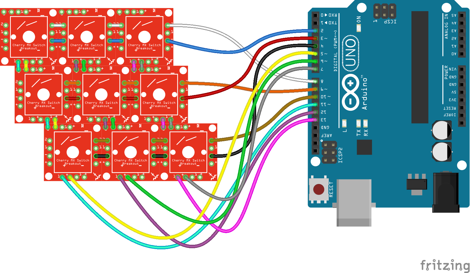
| Row/Column Name | Breakout Label | Arduino Pin |
|---|---|---|
| LED Row 1 | - | 2 |
| LED Row 2 | - | 3 |
| LED Row 3 | - | 4 |
| LED Column 1 | + | 5 |
| LED Column 2 | + | 6 |
| LED Column 3 | + | 7 |
| Switch Row 1 | 2 | 8 |
| Switch Row 2 | 2 | 9 |
| Switch Row 3 | 2 | 10 |
| Switch Column 1 | 1 | 11 |
| Switch Column 2 | 1 | 12 |
| Switch Column 3 | 1 | 13 |
Then copy this code and upload:
Note: This example assumes you are using the latest version of the Arduino IDE on your desktop. If this is your first time using Arduino, please review our tutorial on installing the Arduino IDE.
If you have not previously installed an Arduino library, please check out our installation guide.language:c
/* Button/LED Matrix Scanning Example - 3x3 Keypad
Code derived from Button Pad Hookup Guide Example 2
by Byron Jacquot @ SparkFun Electronics
https://learn.sparkfun.com/tutorials/button-pad-hookup-guide#exercise-2-monochrome-plus-buttons
*/
//////////////////////
// Config Variables //
//////////////////////
#define NUM_LED_COLS (3) // Number of LED columns (+, anode)
#define NUM_LED_ROWS (3) // Number of LED rows (-, cathode)
#define NUM_BTN_COLS (3) // Number of switch columns (isolating diode anode)
#define NUM_BTN_ROWS (3) // Number of switch rows (isolating diode cathode)
// Debounce built-in to the code. This sets the number of button
// high or low senses that trigger a press or release
#define MAX_DEBOUNCE (3)
////////////////////
// Hardware Setup //
////////////////////
static const uint8_t btnRowPins[NUM_BTN_ROWS] = {8, 9, 10}; // Pins connected to switch rows (2)
static const uint8_t btnColPins[NUM_BTN_COLS] = {11, 12, 13}; // Pins connected to switch columns (1)
static const uint8_t ledRowPins[NUM_LED_ROWS] = {2, 3, 4}; // Pins connected to LED rows (-)
static const uint8_t ledColPins[NUM_LED_COLS] = {5, 6, 7}; // Pins connected to LED cols (+)
//////////////////////
// Global Variables //
//////////////////////
static bool LED_buffer[NUM_LED_COLS][NUM_LED_ROWS]; // Keeps track of LED states
static int8_t debounce_count[NUM_BTN_COLS][NUM_BTN_ROWS]; // One debounce counter per switch
void setup()
{
Serial.begin(9600);
setupLEDPins();
setupSwitchPins();
// Initialize the debounce counter array
for (uint8_t i = 0; i < NUM_BTN_COLS; i++)
{
for (uint8_t j = 0; j < NUM_BTN_ROWS; j++)
{
debounce_count[i][j] = 0;
}
}
// Initialize the LED buffer
for (uint8_t i = 0; i < NUM_LED_COLS; i++)
{
for (uint8_t j = 0; j < NUM_LED_ROWS; j++)
{
LED_buffer[i][j] = 0; // All LED's off
}
}
}
void loop()
{
scan();
}
static void scan()
{
// Each run through the scan function operates on a single row
// of the matrix, kept track of using the currentRow variable.
static uint8_t currentRow = 0;
uint8_t i, j; // for loop counters
// Select current row, and write all components on that row LOW.
// That'll set the LED anode's LOW, and write the switch "2" pins LOW.
// If diodes were added, "2' should be connected to the diode cathode
digitalWrite(btnRowPins[currentRow], LOW);
digitalWrite(ledRowPins[currentRow], LOW);
// Look at the LED_buffer variable along this row.
// If any column is 1, turn the LED on.
// Otherwise LED will be left off
for (i = 0; i < NUM_LED_COLS; i++)
{
if (LED_buffer[currentRow][i])
{
digitalWrite(ledColPins[i], HIGH); // Turn LED on
}
}
// Scan through switches on this row:
for ( j = 0; j < NUM_BTN_COLS; j++)
{
// Read the button. If it's pressed, it should be LOW.
if (digitalRead(btnColPins[j]) == LOW)
{
if ( debounce_count[currentRow][j] < MAX_DEBOUNCE)
{ // Increment a debounce counter
debounce_count[currentRow][j]++;
if ( debounce_count[currentRow][j] == MAX_DEBOUNCE )
{ // If debounce counter hits MAX_DEBOUNCE (default: 3)
// Trigger key press -- Do anything here...
Serial.print("Key pressed ");
Serial.println((currentRow * NUM_BTN_COLS) + j);
LED_buffer[currentRow][j] = 1; // Set LED to turn on next time through
}
}
}
else // Otherwise, button is released
{
if ( debounce_count[currentRow][j] > 0)
{
debounce_count[currentRow][j]--; // Decrement debounce counter
if ( debounce_count[currentRow][j] == 0 )
{ // If debounce counter hits 0
// Trigger key release -- Do anything here...
Serial.print("Key released "); // Trigger key release
Serial.println((currentRow * NUM_BTN_COLS) + j);
LED_buffer[currentRow][j] = 0; // Set LED to turn off next time through
}
}
}
}
// Once done scanning, de-select the switch and LED rows
// by writing them HIGH.
digitalWrite(btnRowPins[currentRow], HIGH);
digitalWrite(ledRowPins[currentRow], HIGH);
// Then turn off any LEDs that might have turned on:
for (i = 0; i < NUM_LED_ROWS; i++)
{
digitalWrite(ledColPins[i], LOW);
}
// Increment currentRow, so next time we scan the next row
currentRow++;
if (currentRow >= NUM_LED_ROWS)
{
currentRow = 0;
}
}
static void setupLEDPins()
{
uint8_t i;
// LED drive rows - written LOW when active, HIGH otherwise
for (i = 0; i < NUM_LED_ROWS; i++)
{
pinMode(ledRowPins[i], OUTPUT);
digitalWrite(ledRowPins[i], HIGH);
}
// LED select columns - Write HIGH to turn an LED on.
for (i = 0; i < NUM_LED_COLS; i++)
{
pinMode(ledColPins[i], OUTPUT);
digitalWrite(ledColPins[i], LOW);
}
}
static void setupSwitchPins()
{
uint8_t i;
// Button drive rows - written LOW when active, HIGH otherwise
for (i = 0; i < NUM_BTN_ROWS; i++)
{
pinMode(btnRowPins[i], OUTPUT);
// with nothing selected by default
digitalWrite(btnRowPins[i], HIGH);
}
// Buttn select columns. Pulled high through resistor. Will be LOW when active
for (i = 0; i < NUM_BTN_COLS; i++)
{
pinMode(btnColPins[i], INPUT_PULLUP);
}
}
Whenever you press a switch, the LED on that switch should also light up. Releasing the switch turns the LED off.
Adapting the Code
The code is adaptable for larger or smaller matrices, with a few modifications towards the top of the sketch.
Modify the number of rows or columns in the Config Variables section:
language:c
//////////////////////
// Config Variables //
//////////////////////
#define NUM_LED_COLS (3) // Number of LED columns (+, anode)
#define NUM_LED_ROWS (3) // Number of LED rows (-, cathode)
#define NUM_BTN_COLS (3) // Number of switch columns (diode anode)
#define NUM_BTN_ROWS (3) // Number of switch rows (diode cathode)
And/or convert the pin connections in the Hardware Setup section:
language:c
////////////////////
// Hardware Setup //
////////////////////
static const uint8_t btnRowPins[NUM_BTN_ROWS] = {8, 9, 10}; // Pins connected to switch rows (2)
static const uint8_t btnColPins[NUM_BTN_COLS] = {11, 12, 13}; // Pins connected to switch columns (1)
static const uint8_t ledRowPins[NUM_LED_ROWS] = {2, 3, 4}; // Pins connected to LED rows (-)
static const uint8_t ledColPins[NUM_LED_COLS] = {5, 6, 7}; // Pins connected to LED cols (+)
If you've added ghost-prevention diodes, keep in mind that the switch's "1" pins (organized as the columns) must be at a higher potential than the row, "2" pins.
To scan the keypad matrix, we recommend pulling the row pins high using a pull-up resistor (often internal to I/O pins). Then progressively pulling the column pins to ground and checking which of the rows, if any, are pulled low as well.