Cherry MX Switch Breakout Hookup Guide
Introduction
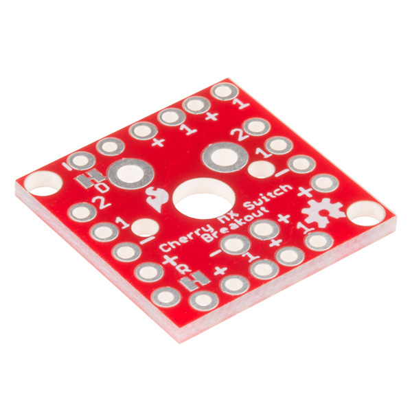
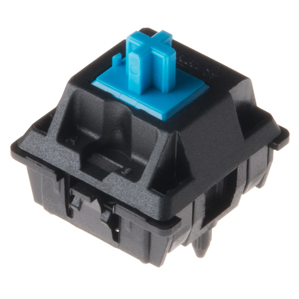
Cherry MX Keyswitches are top-of-the-line mechanical keyboard switches. They're satisfyingly "clicky", reliable up to tens-of-millions of key presses, and an essential component in gaming and programming keyboards. To help make the switches more easily adaptable to breadboard or perfboard-based projects, we created the SparkFun Cherry MX Switch Breakout.
In addition to breaking out the switch contacts to breadboard-compatible headers, the breakout also provides access to an optional switch-mounted LED. Plus, the pin break-outs are designed with keyboard matrix-ing in mind, so you can interconnect as many boards as you'd like into a row-column configuration, keeping the I/O-pin requirements as low as possible.
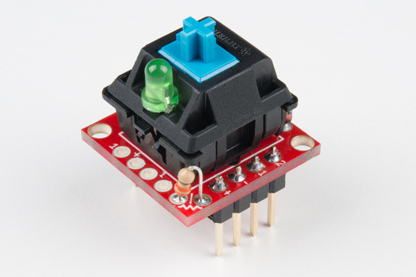 |
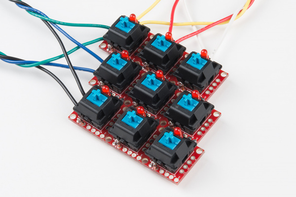 |
| Cherry MX Switch in action | Matrixed Configuration |
The Cherry MX Switch Breakout is a perfect prototyping tool for input devices ranging from a single key to fully-custom 101-key keyboards.
Covered In This Tutorial
This tutorial documents the SparkFun Cherry MX Switch Breakout, providing an overview of the breakout, plus some assembly and usage tips. It's broken down into a few sections, which you can navigate around using the buttons on the right.
Or use these links below to skip ahead:
- Hardware Overview -- A breakdown of the Cherry MX Switch Breakout Board features.
- Assembly Tips -- Tips for adding headers, wires, resistors, and diodes to the breakout board.
- Testing the Circuit -- A simple circuit to test the switch, LED, and any other components you may add on.
- Matrixing Breakouts -- A guide to combining two or more breakout boards into a row/column matrix, and scanning them with an Arduino.
Bill of Materials
In addition to the Cherry MX Switch there are a few additional items you may want to add on to the Breakout Board.
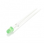
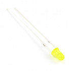
3mm LEDs can be placed inside the switch. Pick any color you please: red, green, yellow, or cycling.
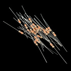
The breakout board also provides a footprint for an optional LED-current-limiting resistor. 1/6W PTH resistors, like these 330Ω's, are recommended.
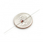
If you're matrixing multiple breakout boards together, you may want to add a small-signal diode to the board to help isolate the switches and prevent any possible "ghosting". Standard 1N4148 diodes should do the trick for this.
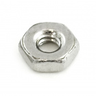
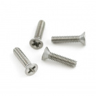
If you need to tie the board down, it has mounting holes designed to fit 2-56 screws and nuts.
Screw - Flat Head (3/8", 2-56)
PRT-08992Resistor 330 Ohm 1/6 Watt PTH - 20 pack
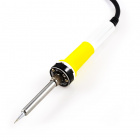
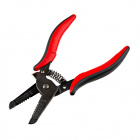
COM-11507You'll need soldering tools, including a soldering iron and solder. Other tools, like wire strippers, flush cutters, and a third hand, can also be helpful.
Flush Cutters - Xcelite
TOL-14782Finally, headers or wire will help connect the breakout board to your breadboard or development platform.
Suggested Reading
This hookup guide relies on some beginner-level electronics knowledge. If any of the subjects below sound foreign to you, consider checking out that tutorial first:
