Cherry MX Switch Breakout Hookup Guide
 jimblom
 Assembly Tips
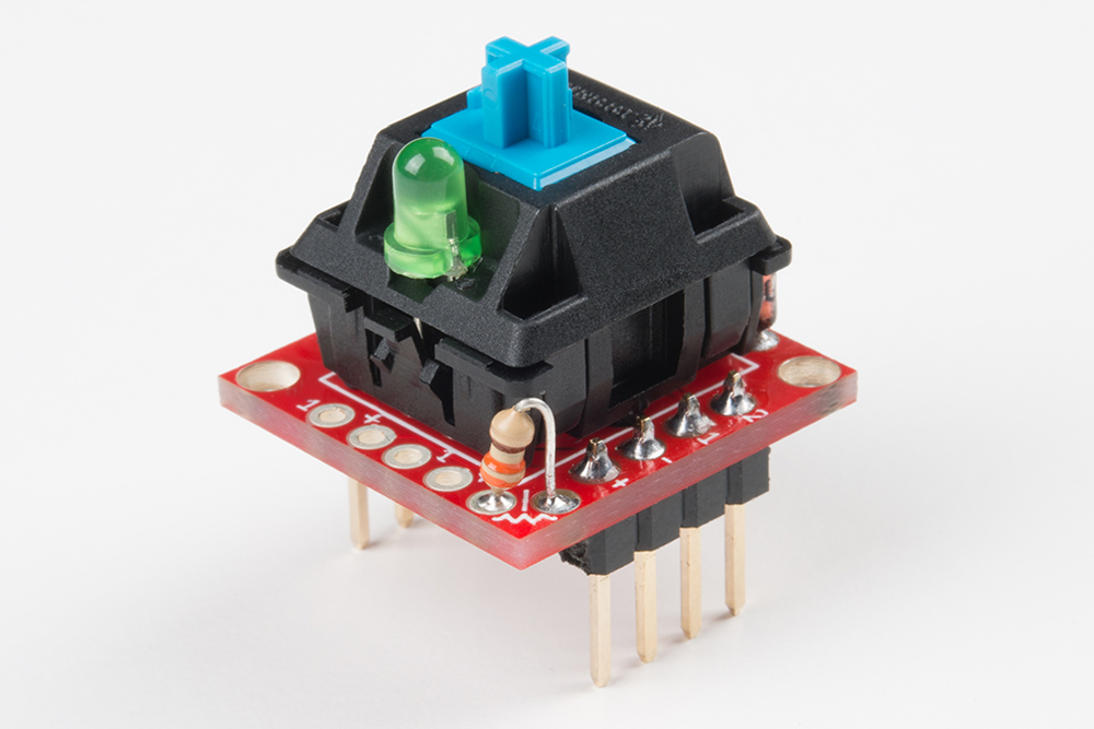
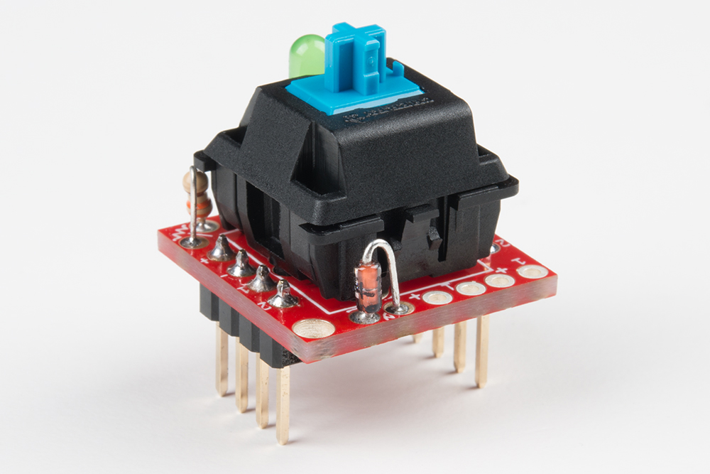
To use the breakout board, at a bare minimum you'll need to solder the Cherry MX Switch and either headers or wires to the "1" and "2" pins. Male headers work well for most breadboarding applications, while solid-core or stranded wire work well if you're wiring the breakout up to something afar.


There are plenty of other addon options, including a 3mm LED, current-limiting resistor, and switch isolating diodes, which are all documented below.
3mm LED
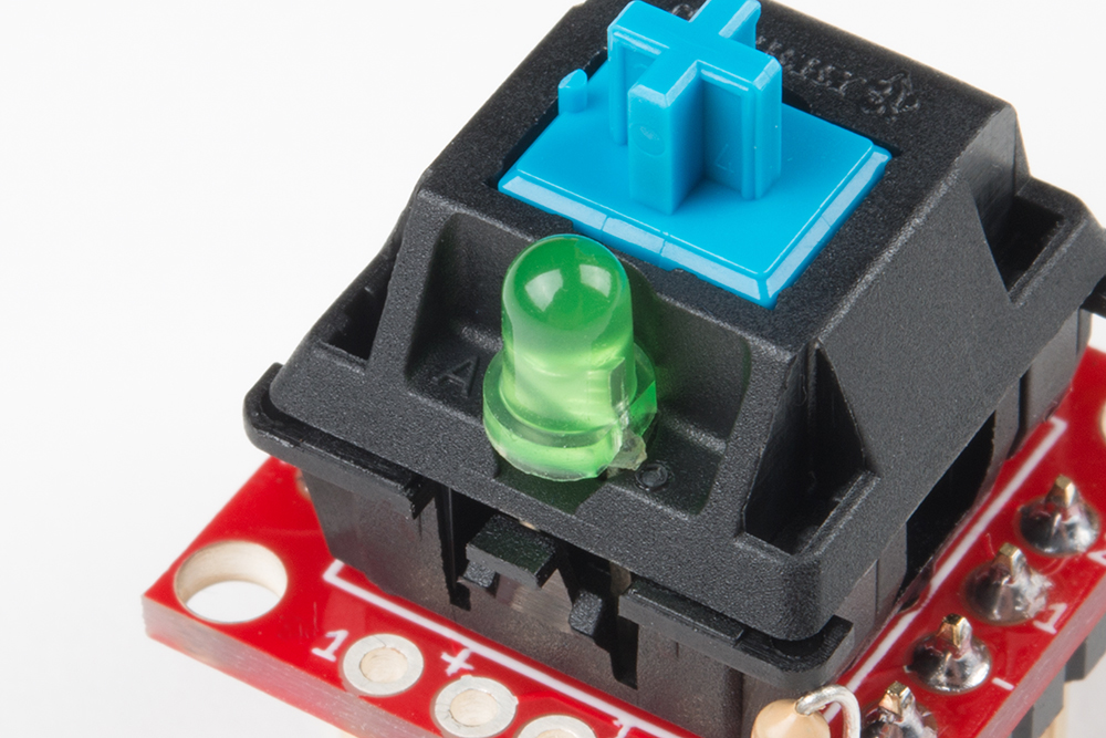
Most Cherry MX Switches -- including the blue, MX1A-E1NW switch we carry -- have a recess in their body designed to fit a small 3mm LED.
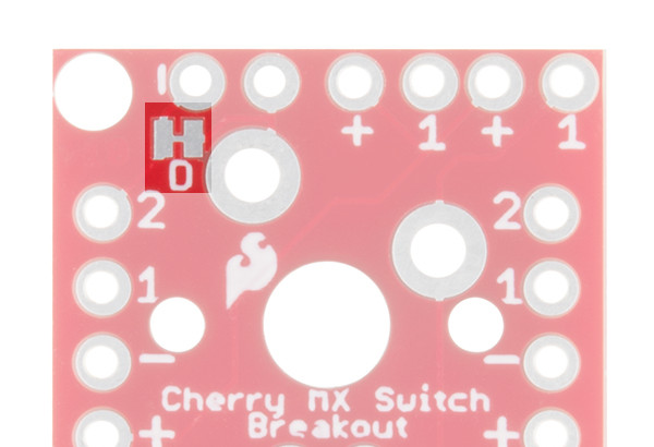
An "A" on the top side of the switch and a diode symbol on the backside both show the recommended polarity of the LED.

To add an LED to the switch, insert the anode and cathode legs of the LED into their respective pins -- the LED's longer, anode leg should be inserted into the "A" pin -- then flip the board over, and solder the LED to the breakout board.
Adding a Current-Limiting Resistor
If you're adding an LED to the switch, more likely than not, you'll need a current-limiting resistor. The breakout provides a resistor footprint, in-line with the LED. You'll find the resistor pads on the bottom-right corner of the board.
To connect an LED to the board, bend one of the resistor legs so it's parallel with the other. Then insert both legs into the board like so:
You'll also need to cut the "R" jumper on the back side of the board, which might be easier to do before you solder anything. A hobby knife and a steady hand should do the trick.
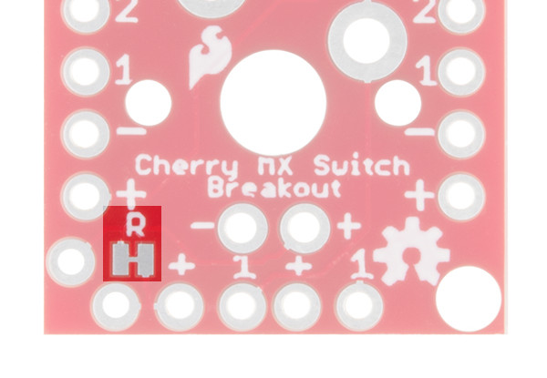
By default, the board has a short across the current-limiting resistor. Cutting this jumper removes the short, and functionally adds the resistor to the circuit.
Ghost-Prevention Diode
If you plan on interconnecting four-or-more breakouts -- creating a row/column matrix of switches -- you may also want to consider adding a small-signal diode to help prevent "ghosting". The 1N4148 small-signal diode is perfectly fit for this task.
Switch Matrix Ghosting
"Ghosting" is a problem that can adversely affect the detection of multiple, simultaneous button presses. Without diode protection, certain combinations of simultaneous button-presses can cause one-or-more un-actuated buttons to appear pressed ("ghosted"). The result is a false-positive key-press, which can cause undesired behavior in a project.
To avoid button ghosting, small-signal diodes can be placed in-circuit, after every key. The diode prevents a key's signal from "backfeeding" back through the line.
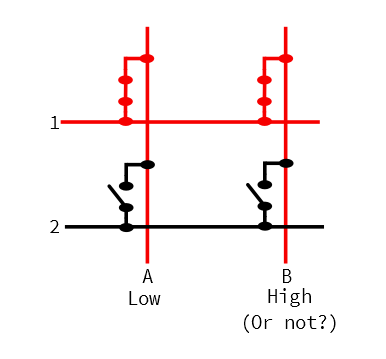
While the diode does prevent ghosting, it does place certain restrictions on your button-press detection. It forces the switch contact on the diode's anode (positive) side to be at a higher voltage than the other contact, as the switch can only conduct meaningful current in one direction.
For more on keypad ghosting, check out Byron's explanation in the Button Pad Hookup Guide.
A small, "vertical" diode footprint is broken out in the upper-right corner of the board. Near one of the pads in this footprint, a small, white line designates which pin should be connected to the diode's cathode (negative) pin.
To solder a diode into the board, bend the anode leg down, so it's parallel with the cathode leg. Then insert the diode into the board -- making sure to place the cathode leg (usually indicated by a black bar) into the marked hole.
You'll also need to cut the "D" jumper on the back side of the board -- otherwise the diode will be shorted over. (This may be easier if you do it before soldering anything.)
Like the resistor, the breakout shorts across the diode. Cutting this jumper removes the short and functionally adds the diode to the circuit.
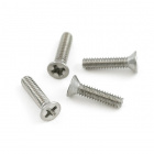
Mounting Hole Size
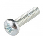
A pair of mounting holes are provided on opposite corners of the breakout board. These holes are designed to fit 2-56 (3/8") screws. Flat heads are recommended, though rounded heads can work as well.
Screw - Flat Head (3/8", 2-56)
PRT-08992If you're going to be doing a lot of jamming on your keyboard, you'll want it tied down!