Cherry MX Switch Breakout Hookup Guide
 jimblom
Hardware Overview
While it may seem like a simple breakout, the Cherry MX Switch Breakout board is a little over-engineered. Here's a quick breakdown of the pin breakouts and additional features of the board.
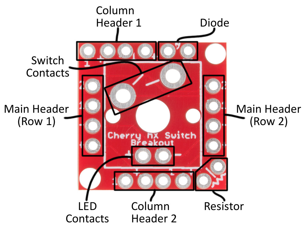
Breakout Pin Labels
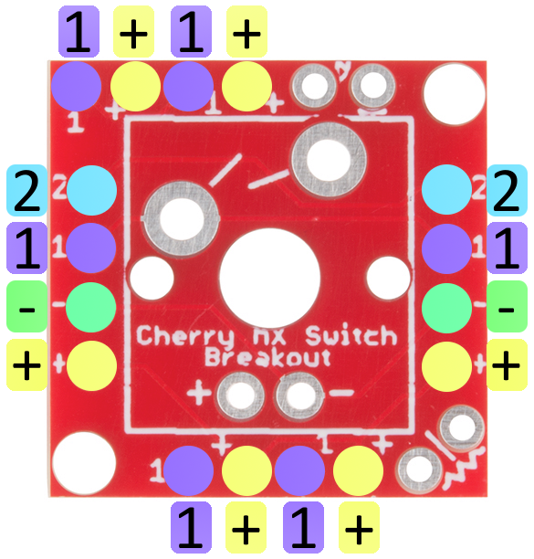
Up to four pins are used to interact with the Cherry MX Switch -- two for the switch contacts and two for the optional LED. These pins are broken out on all sides of the board, labeled either "1", "2", "+", or "-". Those labels are short for:
| Pin Label | Pin Description |
|---|---|
| 1 | Switch contact 1 |
| 2 | Switch contact 2 |
| + | LED anode |
| - | LED cathode |
If you only want to use the switch, the pins labeled "1" and "2" should be all you need. If you're integrating a 3mm LED, the LED's anode and cathode will be accessible on the "+" and "-" pins respectively.
Header Pairs
Every side of the breakout board is equipped with a four-pin header (don't confuse them with the diode or resistor pins), but not all of these headers are created equally! Two headers break out all four pins, while the other two headers only break out the LED anode and one of the switch contacts.
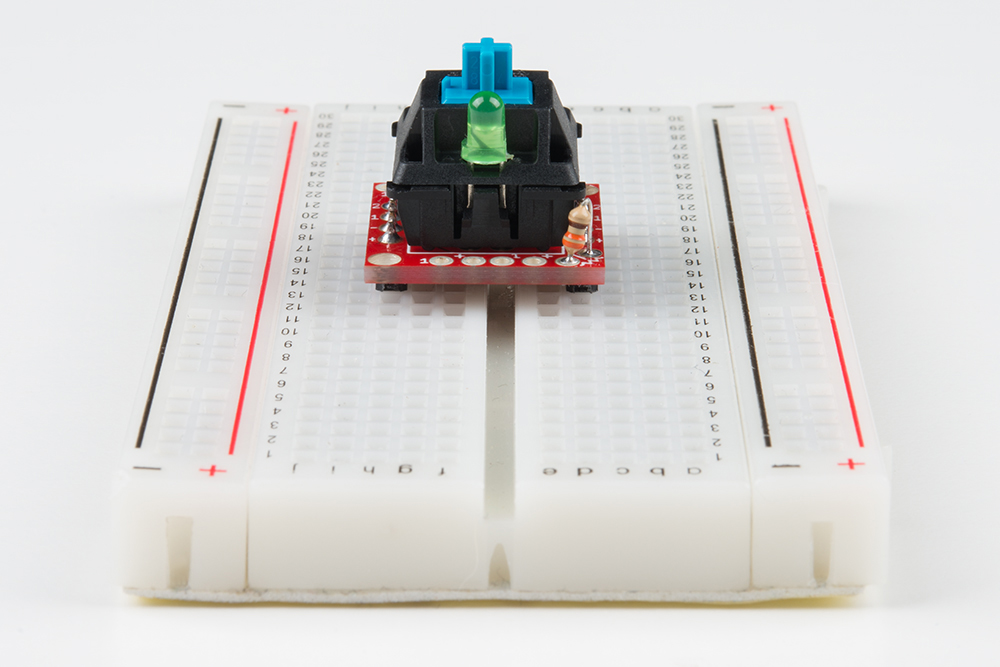
The pair of headers on the left and right sides of the board break out all four pins. These are intended for primary use. You can solder male pins into both of these headers, and plug the switch into a breadboard.
The pair of headers breaking only the LED anode and switch contact 1 are designed for keypad matrices, where multiple boards are connected in row/column pairs. More on this later in the tutorial.