CAN-BUS Shield Hookup Guide
 Toni_K, Member #399586
Example Code
There are several different example sketches included in the library, each with different functionality.
SparkFun_CAN_Demo - This sketch allows you test the CAN functionality of the board by itself.
SparkFun_ECU_Demo - This sketch runs all hardware on the shield together, and logs CAN data and GPS data to the SD card, while outputting data over the serial LCD. You will need to instally the TinyGPS library and the SD library for this to work.
SparkFun_GPS_Demo- This sketch runs through using the GPS module. You will need to instally the TinyGPS library for this to work.
SparkFun_Joystick_Demo - This quick sketch allows you to test the functionality of the on board joystick.
SparkFun_SD_Demo - This sketch allows you to verify and test functionality of the microSD socket on board. You will need to install the SD library for this to work.
SparkFun_SerialLCD_Demo - A quick sketch to make sure your serial LCD screen is functioning properly.
CAN_Read_Demo - A very stripped down sketch to read any and all data coming out of the CAN bus.
CAN_Write_Demo - A basic demo for writing to the CAN bus.
For our example, we are going to run through the ECU_Demo sketch, but feel free to use or modify the other sketches. If you decided to not plug in the microSD card, GPS unit and LCD screen, you should instead run the CAN_Demo.
ECU_Demo
This sketch shows off the basic functionality of each part of the shield. Once you've installed the library, open up Arduino and upload this code to your RedBoard.
Check through the comments in the code for details of what each section does, but the general flow of the sketch is as follows:
- The Arduino initializes the pins, variables, and baud rates for the GPS, LCD, uSD card, and CAN-Bus.
- In the setup loop, each device is started, and verified that everything is connected as it should. Both the CAN-Bus and uSD card will print either success or failure messages to the LCD screen.
- The shield will wait for the user to click the joystick to begin collecting data off of the GPS module and the CAN-Bus.
- Once the user has clicked to begin logging, the CAN-Bus will poll for the engine RPM, and will write the latitude, longitude, and GPS speed. A message that the unit is logging will appear on the LCD screen, and the actual engine RPM will be printed to the Serial monitor. The data collected is written to the uSD card.
- Each loop, the code checks if the user has clicked the joystick. If so, the unit stops logging.
    /****************************************************************************
    ECU CAN-Bus Reader and Logger

    Toni Klopfenstein @ SparkFun Electronics
    September 2015
    https://github.com/sparkfun/CAN-Bus_Shield

    This example sketch works with the CAN-Bus shield from SparkFun Electronics.

    It enables reading of the MCP2515 CAN controller and MCP2551 CAN-Bus driver.
    This sketch also enables logging of GPS data, and output to a serial-enabled LCD screen.
    All data is logged to the uSD card.

    Resources:
    Additional libraries to install for functionality of sketch.
    -SD library by William Greiman. https://github.com/greiman/SdFat

    Development environment specifics:
    Developed for Arduino 1.65

    Based off of original example ecu_reader_logger by:
    Sukkin Pang
    SK Pang Electronics www.skpang.co.uk

    This code is beerware; if you see me (or any other SparkFun employee) at the local,
    and you've found our code helpful, please buy us a round!

    For the official license, please check out the license file included with the library.

    Distributed as-is; no warranty is given.
    *************************************************************************/

    //Include necessary libraries for compilation
    #include
    #include
    #include
    #include
    #include

    //Initialize uSD pins
    const int chipSelect = 9;


    //Initialize lcd pins
    SoftwareSerial lcd(3, 6);

    //Initialize GPS pins
    SoftwareSerial uart_gps(4,5);

    // Define Joystick connection pins
    #define UP     A1
    #define DOWN   A3
    #define LEFT   A2
    #define RIGHT  A5
    #define CLICK  A4

    //Define LED pins
    #define LED2 8
    #define LED3 7

    //Define baud rates. GPS should be slower than serial to ensure valid sentences coming through
    #define GPSRATE 4800
    #define LCD_Rate 115200

    //Create instance of TinyGPS
    TinyGPS gps;

    //Declare prototype for TinyGPS library functions
    void getgps(TinyGPS &gps);

    //Declare GPS variables
    float latitude;
    float longitude;
    int year;
    byte month;
    byte day;
    byte hour;
    byte minute;
    byte second;
    byte hundredths;
    float gps_speed;


    //Declare SD File
    File dataFile;

    //Declare CAN variables for communication
    char *EngineRPM;
    char buffer[64];  //Data will be temporarily stored to this buffer before being written to the file

    //Define LCD Positions
    #define COMMAND 0xFE
    #define CLEAR   0x01
    #define LINE1  0x80
    #define LINE2  0xC0


    //********************************Setup Loop*********************************//
    void setup() {
      //Initialize Serial communication for debugging
     // Serial.begin(9600);
      //Serial.println("ECU Demo");

      //Begin LCD serial communication
      lcd.begin(9600);

      //Begin GPS communcation
      uart_gps.begin(GPSRATE);

      //Initialize pins as necessary
      pinMode(chipSelect, OUTPUT);
      pinMode(CLICK,INPUT);
      pinMode(LED2, OUTPUT);
      pinMode(LED3, OUTPUT);

      //Pull analog pins high to enable reading of joystick movements
      digitalWrite(CLICK, HIGH);

      //Write LED pins low to turn them off by default
      digitalWrite(LED2, LOW);
      digitalWrite(LED3, LOW);

      //Initialize CAN Controller
      if(Canbus.init(CANSPEED_500))  /* Initialize MCP2515 CAN controller at the specified speed */
      {
        clear_lcd();
        lcd.print("CAN Init ok");
        //Serial.println("CAN Init Ok");
        delay(1500);
      }
      else
      {
        lcd.print("Can't init CAN");
        //Serial.println("Can't init CAN");
        return;
      }

       //Check if uSD card initialized
      if (!SD.begin(chipSelect)) {
        //Serial.println("uSD card failed to initialize, or is not present");
        clear_lcd();
        lcd.print("uSD failed.");
        return;
      }
      else{
          //Serial.println("uSD card initialized.");
          clear_lcd();
          lcd.print("uSD success!");
          delay(1500);
      }

      //Print menu to LCD screen
      clear_lcd();
      lcd.print("Click to begin");
      lcd.write(COMMAND);
      lcd.write(LINE2);
      lcd.print("Logging Data");

      while(digitalRead(CLICK)==HIGH)
      {
         //Wait for user to click joystick to begin logging
      }

      delay(1000);

    }

    //********************************Main Loop*********************************//
    void loop(){

      while(digitalRead(CLICK)==HIGH){

          digitalWrite(LED3, HIGH); //Turn on LED to indicate CAN Bus traffic

          Canbus.ecu_req(ENGINE_RPM,buffer); //Request engine RPM
          EngineRPM = buffer;
          //Serial.print("Engine RPM: "); //Uncomment for Serial debugging
          //Serial.println(buffer);
          delay(100);


          digitalWrite(LED3, LOW); //Turn off LED3
          delay(500);

        File  dataFile = SD.open("data.txt", FILE_WRITE); //Open uSD file to log data

          //If data file can't be opened, throw error.
          if (!dataFile){
              clear_lcd();
            lcd.print("Error opening");
            lcd.write(COMMAND);
            lcd.write(LINE2);
            lcd.print("data.txt");
            while(1);
            }

            clear_lcd();
            lcd.print("Logging.Click");
            lcd.write(COMMAND);
            lcd.write(LINE2);
            lcd.print("to stop logging");

            if(uart_gps.available())     // While there is data on the RX pin...
               {
                 digitalWrite(LED2, HIGH); //Signal on D8 that GPS data received.

                 //Print Latitude/Longitude to SD card
                 dataFile.print("Lat/Long: ");
                 dataFile.print(latitude,5);
                 dataFile.print(", ");
                 dataFile.println(longitude,5);

                  // Print data and time to SD card
                 dataFile.print("Date: "); dataFile.print(month, DEC); dataFile.print("/");
                 dataFile.print(day, DEC); dataFile.print("/"); dataFile.print(year);
                 dataFile.print("  Time: "); dataFile.print(hour, DEC); dataFile.print(":");
                 dataFile.print(minute, DEC); dataFile.print(":"); dataFile.print(second, DEC);
                 dataFile.print("."); dataFile.println(hundredths, DEC);

                  //Print GPS speed to SD card
                  dataFile.print("GPS Speed(kmph): ");
                  dataFile.println(gps_speed);

                 digitalWrite(LED2, LOW); //Turn off D8 LED.
               }

            dataFile.print("Engine RPM: ");
            dataFile.println(EngineRPM);

            dataFile.println();
            dataFile.flush();
            dataFile.close();   //Close data logging file
          }
          clear_lcd();
          lcd.print("Logging stopped.");
          while(1); //Stop logging if joystick is clicked

        }

        //********************************LCD Functions*********************************//
        void clear_lcd(void)
        {
          lcd.write(COMMAND);
          lcd.write(CLEAR);
        }

        //********************************GPS Functions*********************************//
        void getgps(TinyGPS &gps)
        {
          // Receive GPS latitude/longitude
          gps.f_get_position(&latitude, &longitude);

          //Call function to receive date and time from GPS
          gps.crack_datetime(&year,&month,&day,&hour,&minute,&second,&hundredths);

          //Also collect gps_speed
          gps_speed = gps.f_speed_kmph();

        }
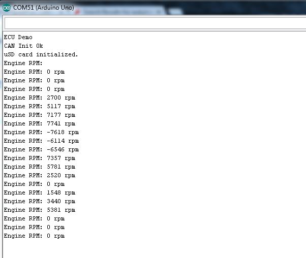
If you've uncommented the lines for serial debugging, you should see something like this:
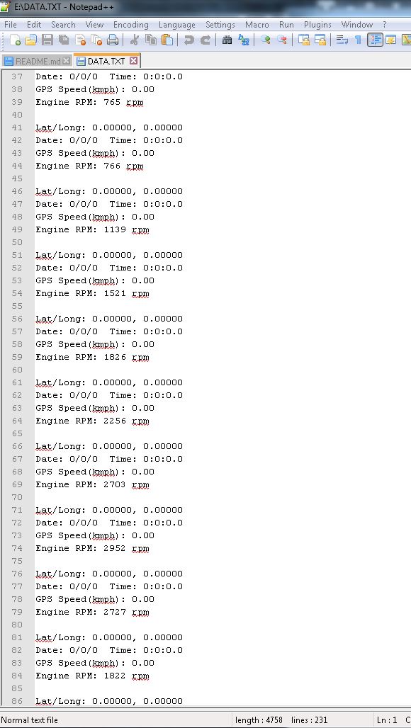
Once you have collected some readings, you can pull your uSD card out and take a look at the data recorded. There should be a file on your uSD card called "DATA.TXT", and it should include information like the following:
Once you've verified data is being stored to the uSD card, you're good to go! You've successfully interfaced with your vehicle's CAN-Bus and can now start digging into diagnostic codes and building projects around your engine's data.