CAN-BUS Shield Hookup Guide
 Toni_K, Member #399586
Hardware Overview
There are several features to be aware of on the CAN-Bus Shield.
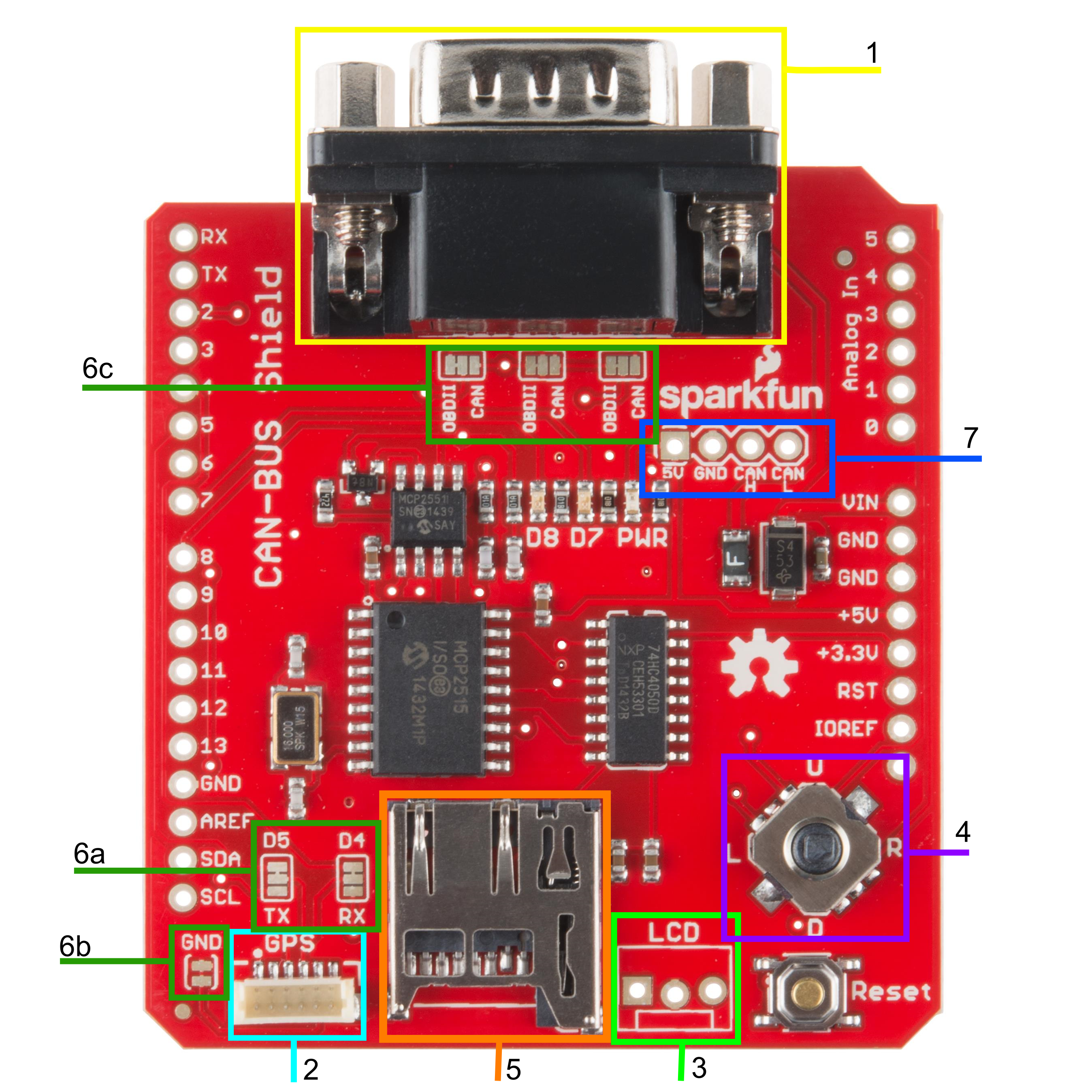
1. DB9 Connector
The primary hardware feature on this shield is the DB9 connector. This allows you to interface to OBD-II ports with a DB9 to OBD-II cable.
2. GPS Connector
The GPS connector on-board is a 6-pin, JST SH compatible connector. The board is designed to interface with either the EM-506 GPS Receiver, or the GP-735 GPS Receiver. The GND jumper allows the user to modify the GPS connector for units that do not have a GND connection on pin 5 of the connector.
3. LCD Connector
The LCD footprint on the shield is compatible with a male 3-pin JST connector and can interface with any of our serial LCD screens. The connection is designed for 5V LCDs, so don't accidentally plug in a 3.3V option! The pin order is 5V, GND, and RX/D6 when looking at the shield straight on.
4. JoyStick
The joystick included on the shield provides a basic user interface for controlling screen displays or selecting CAN scan settings. The connector gives 5 basic user options:
- Up
- Down
- Left
- Right
- Click selection
5. microSD Slot
This slot provides the user with the option of storing collected data onto a microSD card. Data collected can include user input on the joystick, CAN-Bus information collected, LCD outputs, or general I/O data.
6. Jumpers
There are six jumpers present on the CAN-Bus Shield.
6a. SJ1 and SJ2 - These two jumpers allow the user to select between UART and Software Serial for the GPS unit to communicate with the Arduino.
6b. SJ3 - This allows the user to separate pin 5 on the GPS connector from the
GNDline. This jumper comes closed by default.6c. SJ4, SJ5, and SJ6 - These three jumpers allow the user to select the DB9 pin configuration between OBD-II and CAN. The jumpers are defaulted to the OBD-II configuration that matches SparkFun's OBD-II to DB9 cable.
For reference, here are the configuration options showing which pins are selected on the DB9 connector for each setting.
| Bus Lines | CAN Pins | OBD-II Pins | Solder Jumper |
|---|---|---|---|
| CAN-H | Pin 7 | Pin 3 | SJ4 |
| CAN-L | Pin 2 | Pin 5 | SJ6 |
| GND | Pin 3 | Pin 2 | SJ5 |
7. CAN Pins
4 CAN lines are broken out to allow you direct access to the raw CAN data coming off of the DB9 connector. These pins are:
- 5V
- GND
- CAN H (CAN HIGH)
- CAN L (CAN LOW)
Again, this data is raw coming off of the CAN-Bus. It has not been filtered through the MCP2515 or the MCP2551 ICs.
Communication Methods
Because of all of the different hardware features on the shield, there are a couple different communication methods used.
SPI - The MCP2515 IC and the microSD slot both communicate with the Arduino via the SPI lines. The CAN
Chip Selectline is located onD10. The SDChip Selectline is connected toD9.Analog In - The joystick is connected to pins A1-A5 on the Arduino. Each direction of the joystick has its own analog input.
Software Serial/UART - The LCD and GPS both communicate over serial lines with the Arduino. The LCD's
RXline connects toD6. The GPS either connects via Software Serial toD4andD5, or to the UART port onD0andD1.