CAN-BUS Shield Hookup Guide
 Toni_K, Member #399586
Hardware Hookup
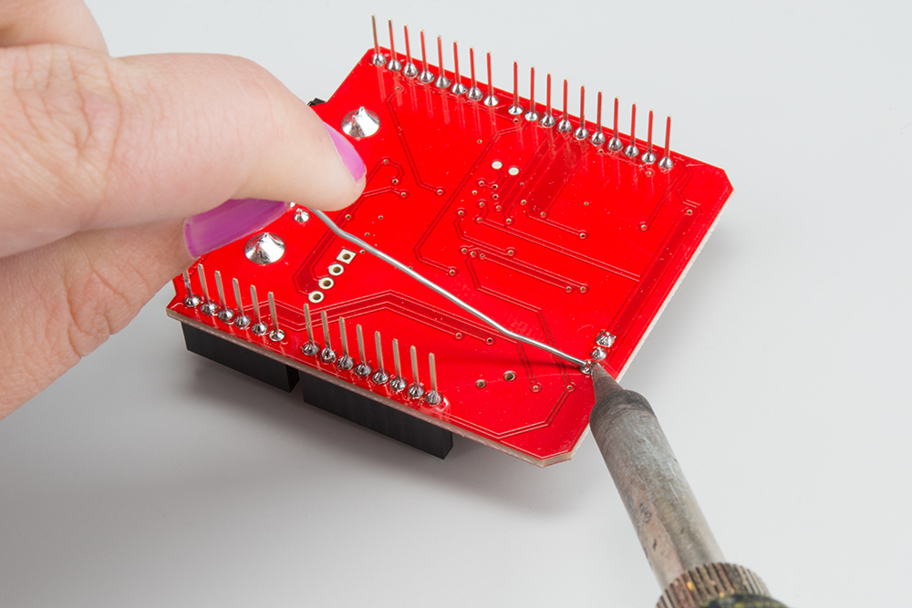
Solder Connectors
To get your CAN-Bus shield hooked up, solder on the Arduino Stackable Headers.
Once those are soldered, consider how you want to connect your LCD screen. You can use either male or female headers with 0.1" spacing, or the JST connector. Solder your interface choice onto the shield at this time as well.
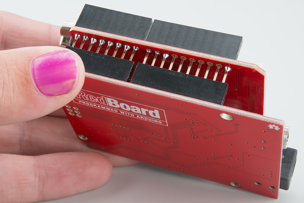
Connect the Brain!
In our case, the brain will be the RedBoard. Insert your shield into the RedBoard. Take your time and go slowly to prevent bending the header pins.
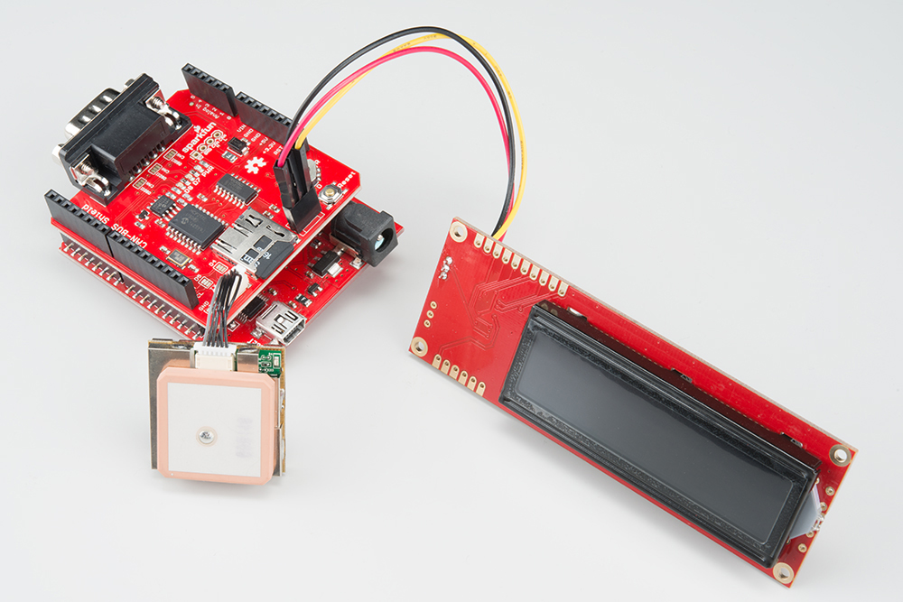
Connect the Extras
We recommend plugging in the GPS unit, LCD screen, and microSD card now. If you don't plan to use any of these features, you can skip this step.
If you're planning on putting your CAN-Bus/RedBoard combination into an enclosure, you may want to consider using an extension cable for the GPS unit. Enclosures can block the satellites from view and lead to spotty GPS functionality, so placing the GPS unit outside of any enclosures should alleviate those issues.
We also recommend connecting your LCD screen at this time. Your method of connecting the LCD screen will depend on what connector you soldered onto the shield previously. Looking the shield straight on, the connections are 5V, GND, and TX, if you are not using the JST connector.
Make sure you use a formatted microSD card. Once all the extras are connected, your circuit should look like the following:
Connect to your CAN-enabled device
This can be a simulator or a vehicle. Plug the DB9 connector into the shield, and plug the DLC connector into the device to which you plan on talking. If your shield+Arduino turns on now, that's ok. The vehicle/simulator can power the board over the cable.
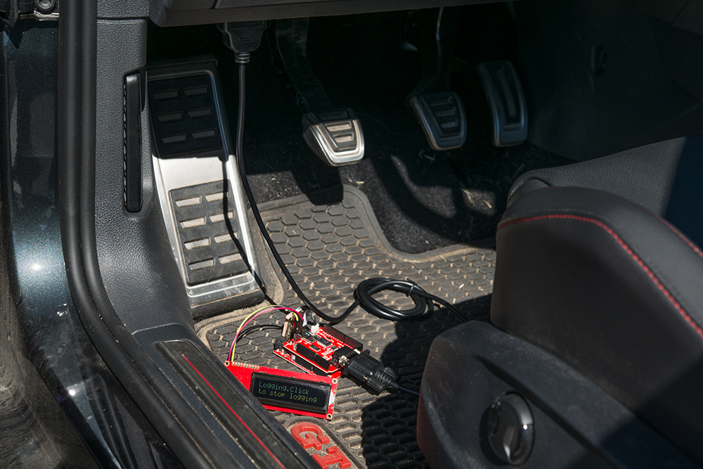
Final Circuit
Once everything is inserted, your circuit should look similar to the following:
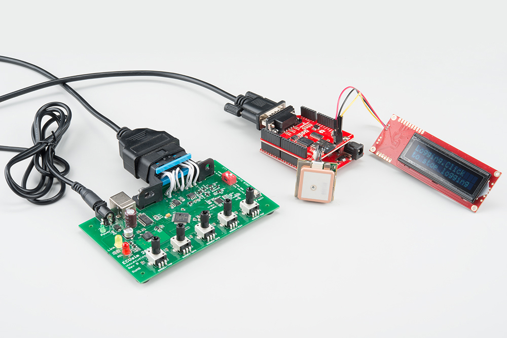
In this case, we show the circuit connected to a CAN simulator. However, you could instead have your circuit connected to a DLC in a CAN-enabled vehicle.