Building the HUB-ee Buggy
This Tutorial is Retired!
This tutorial covers concepts or technologies that are no longer current. It's still here for you to read and enjoy, but may not be as useful as our newest tutorials.
 Nick Poole
If I Only Had a Brain
Two wheels stuck together do not, a robot, make. The Redboard will be our robot brain today. It will read the output of the infrared sensor, and, if it seems too close to an object, will change the direction of travel to avoid collision.
The first matter of business is to connect the "brain" to the robot base, which means that we'll need to solder some headers to the Protoshield. Break off a few headers and solder them to the I/O pins on the Protoshield. They'll act both as an electrical connection and a mechanical connection, keeping the wheels stuck to the brain. The easiest way to make sure your headers are straight when you solder them is to go ahead and stack the shield onto the Redboard. For more shield assembly advice, check out our shield tutorial.
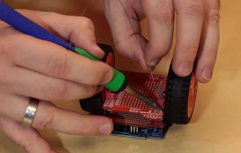
Once you've soldered the headers in place, it's time to make all of the electrical connections from the shield to the wheels and IR sensor. Take your 150mm HUB-ee cable, and cut it in half. I know, it's a painful process for some people to cut through a nice clean cable, but we'll get through this together. Once the cable is bisected, it'll serve as a pair of pigtail connectors. Strip the wire ends, and plug one of the pigtails into each HUB-ee wheel. Go ahead and plug the Infrared Sensor Jumper Wire into the Sharp IR sensor.
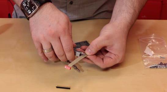
Now, let's solder these jumpers in place. We won't be using the encoders in the HUB-ee wheels for this project, so we don't need to worry about those wires. The HUB-ee Datasheet has a great pinout for the HUB-ee connector that will help us figure out which wires are which.
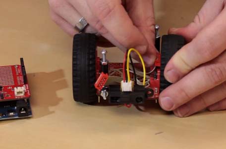
Looks like the wire with a red stripe is ground and the one next to it is power. Make those connections to the GND and 5V pins, respectively, and solder them in place. The next two pins are control inputs and can be connected to any of the Redboard's GPIO pins. I chose D7/D8 for my left wheel and D10/D11 for my right. The next connection to make is the PWM pin which controls the speed of the HUB-ee. Make sure that these are connected to PWM-capable pins on the Redboard. I chose D6 for my left wheel and D9 for my right.
Lastly, the sensor needs to be connected. Simply wire the red and black wires to the 5V and GND pins, respectively, then solder the yellow wire to an analog input pin. I connected mine to A3.
Your HUB-ee Buggy is all wired up now and ready for a power supply...