Everybody loves robots! (Well, except for Sarah Connor.) They come in all shapes and sizes: from small to large; simple to complex. As hobbyists, we're often drawn to more complex robots, but sometimes a simple design is more fun.
Case in point: The HUB-ee Buggy
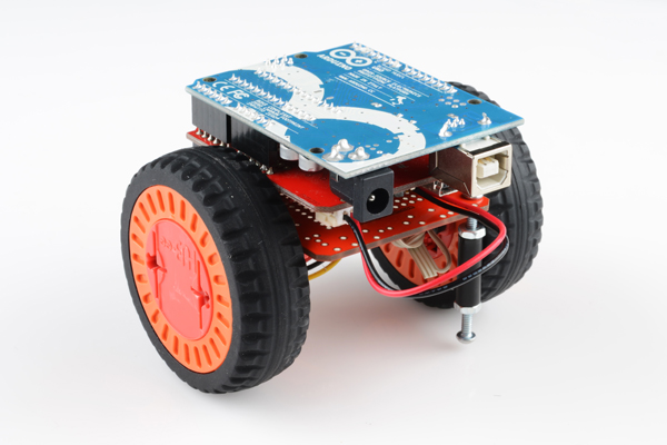
The HUB-ee Buggy robot is a simple two-wheel, object-avoiding robot based on the HUB-ee wheel system. HUB-ee wheels make it possible to build a wheeled robot chassis in a snap by combining the wheel, motor, and driver into a single package. Just bolt a pair of HUB-ee wheels onto a microcontroller, and you've basically made yourself a little robot. That's essentially what we're doing here.
This is an awesome project for starting out with robotics, because it's easy to go from a pile of parts to a rolling robot which can easily be expanded with more sensors, wheels, or complex control code as you learn and progress.
Let's see what we need to get started...
Here are some topics you'll need to be familiar with to make your Hub-ee Buggy.
There are only a handful of parts in the HUB-ee Buggy. Let's start with a list:
There are a few parts you'll need to pick up from your local hardware store:
You'll also need a couple of tools, but you won't need a machine shop by any stretch:
Now that we've gathered everything we need to get started, it's time to do a little planning and figure out what each of these bits are for...
To understand how the HUB-ee Buggy works, it's probably best to start by breaking it down one component at a time:
The wheels, motors and drivers are built into the HUB-ee wheels so it's pretty obvious what function those serve. Without wheels and motors, this robot isn't going anywhere.
The wheels won't know where to go if there's no brain, and that's where the Redboard comes in! The Redboard is an Arduino-compatible development board based on the ATmega328 microcontroller. It'll take input from the Sharp IR sensor and give output to the HUB-ee wheels.
Speaking of the IR sensor, the Sharp GP2Y0A21YK is one of my favorite sensors for simple object detection and avoidance. It's an infrared sensor that detects objects by shining an infrared source and detecting the reflected light. Reading the output is really simple with a microcontroller like the ATmega328 that has a built in ADC because it outputs a voltage. This is how the HUB-ee Buggy will keep from bumping into things and getting stuck.
With only two wheels, the HUB-ee Buggy would tip over if there wasn't some support under it to keep it upright. The simple way to solve that problem is just to add a few stand-offs to prop it up as it scoots around.
The Protoshield PCB is really nice for small projects like this which are basically built on top of a development board. Not only will it allow us to wire things to the Redboard, but it will also serve as a base to which we can attach the wheels.
Finally, we need power to get this whole production moving. Originally, I thought that the LiPo Shield might be a good solution for this, but it just couldn't drive the wheels to my satisfaction. Thus, decided to keep it simple and pop on a AA battery holder.
Alright! Build time!
The first step is to actually mount the HUB-ee wheels to the Protoshield PCB. This will create a little robot base that we can sit the Redboard on top of. The HUB-ee wheels come with a plastic right angle bracket. Go ahead and screw that to the wheel hubs using your M3 bolts. Once you have the wheels connected to the brackets, find a good spot to mount them. About midway on either side of the board worked well for me. Just line up the brackets where you want to put them, and mark the bolt pattern with a pen.
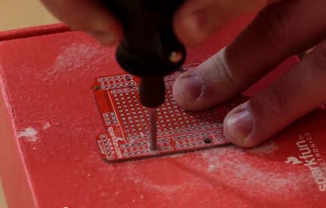
Now take your drill (or rotary tool with a drill bit), and drill holes to mount your wheels. Once you've drilled your holes and you're sure that they line up, go ahead and put the 4-40 bolts through, and connect the wheels to the Protoshield.
At this point you'll have a pretty wobbly little platform so we'll have to add a few standoffs to keep it stable. Drop one of your 1/2" 4-40 bolts through the mounting holes on two opposite corners of the Protoshield. The standoffs aren't quite long enough to keep the bot from falling over, so we need to bolster them with a little bit of bolt length on either side. For the bolt on the "back" of the robot (now's a good time to decide which is the back, I chose the side without the FTDI header), add a nut, and tighten it up the the board. Now put another nut on there, and snug a standoff against the nut. By twisting the nut and the standoff against each other you can force them to stay put on the bolt. Now take another 4-40 bolt, put a nut on it, and screw it into the other end of the standoff. Now the head of that bolt should be touching the ground and keeping the bot upright.
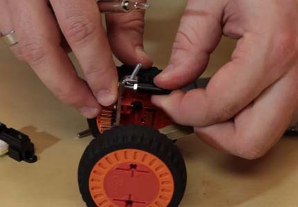
Do the same thing on the opposite corner, but, instead of using a nut to secure the top bolt, use the threaded side of a 4-40 right angle bracket. This bracket will hold our Sharp IR sensor in place. Make your life easier by putting a 1/2" 4-40 screw through the other hole on the angle bracket before using it to secure the standoff bolt.
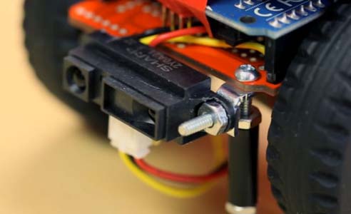
Pick up the Sharp IR Sensor, mount it onto the protruding 4-40 screw, and secure it using a nut. Now that the chassis is complete, let's concern ourselves with a brain...
Two wheels stuck together do not, a robot, make. The Redboard will be our robot brain today. It will read the output of the infrared sensor, and, if it seems too close to an object, will change the direction of travel to avoid collision.
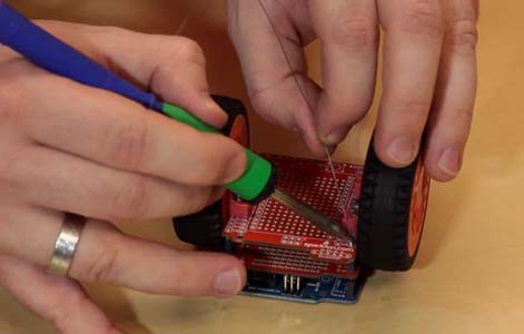
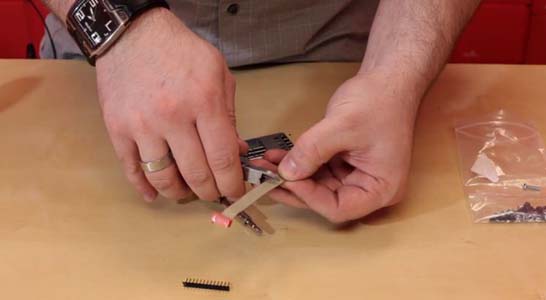
The first matter of business is to connect the "brain" to the robot base, which means that we'll need to solder some headers to the Protoshield. Break off a few headers and solder them to the I/O pins on the Protoshield. They'll act both as an electrical connection and a mechanical connection, keeping the wheels stuck to the brain. The easiest way to make sure your headers are straight when you solder them is to go ahead and stack the shield onto the Redboard. For more shield assembly advice, check out our shield tutorial.
Once you've soldered the headers in place, it's time to make all of the electrical connections from the shield to the wheels and IR sensor. Take your 150mm HUB-ee cable, and cut it in half. I know, it's a painful process for some people to cut through a nice clean cable, but we'll get through this together. Once the cable is bisected, it'll serve as a pair of pigtail connectors. Strip the wire ends, and plug one of the pigtails into each HUB-ee wheel. Go ahead and plug the Infrared Sensor Jumper Wire into the Sharp IR sensor.
Now, let's solder these jumpers in place. We won't be using the encoders in the HUB-ee wheels for this project, so we don't need to worry about those wires. The HUB-ee Datasheet has a great pinout for the HUB-ee connector that will help us figure out which wires are which.
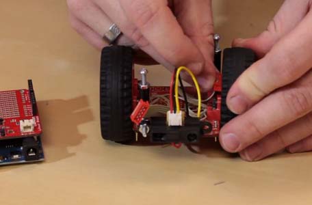
Looks like the wire with a red stripe is ground and the one next to it is power. Make those connections to the GND and 5V pins, respectively, and solder them in place. The next two pins are control inputs and can be connected to any of the Redboard's GPIO pins. I chose D7/D8 for my left wheel and D10/D11 for my right. The next connection to make is the PWM pin which controls the speed of the HUB-ee. Make sure that these are connected to PWM-capable pins on the Redboard. I chose D6 for my left wheel and D9 for my right.
Lastly, the sensor needs to be connected. Simply wire the red and black wires to the 5V and GND pins, respectively, then solder the yellow wire to an analog input pin. I connected mine to A3.
Your HUB-ee Buggy is all wired up now and ready for a power supply...
As I mentioned earlier, I had originally planned on using the LiPower Shield as the power plant for the HUB-ee Buggy, but it just didn't have enough juice to run the motors so I kept it simple with a 4xAA battery holder. The 4xAA to Barrel Jack Connector is perfect for this purpose because we can just plop it on top of the HUB-ee Buggy and plug the barrel connector into the Redboard.
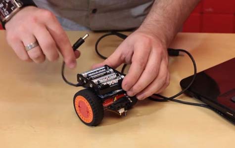
To keep the battery pack in place, I just took a piece of electrical tape and wrapped it around the robot. Now that our 'bot has brains, wheels, and power, we can start programming it!
The HUB-ee Buggy is almost ready to go, but right now it doesn't have any way of avoiding obstacles. We need to tell it what to do when it encounters a wall or other large object. There are a lot of really clever ways to do this, and you can make the code as complicated as you want. In this case, though, we'll keep it basic. The HUB-ee Buggy will keep an eye out for obstacles and turn around when it gets too close to one. This will be achieved by reversing one of the wheels for a few milliseconds.
Plug the Redboard into your computer, and load up this Arduino code:
language:c


// Define the pins to make the code more readable

// Our Sharp IR sensor is connected to A4
#define sharpIR A4

// Our left HUB-ee is connected to D6, D7 and D8
#define leftPWM 6
#define leftIN1 7
#define leftIN2 8

// Our right HUB-ee is connected to D9, D10 and D11
#define rightPWM 9
#define rightIN1 10
#define rightIN2 11

// This is the threshold for how close an object will
// be allowed to get before the HUB-ee Buggy changes
// its direction of travel. You may need to adjust it.
int tooClose = 200;

// This stores the value read from the Sharp IR sensor
int irVal = 0;

void setup() {

  // Set the infrared sensor as an input. This isn't
  // strictly necessary because the ADC is an input
  // by default but it's good practice.
  pinMode(sharpIR, INPUT);

  // Set all of the outputs accordingly
  pinMode(leftPWM, OUTPUT);
  pinMode(leftIN1, OUTPUT);
  pinMode(leftIN2, OUTPUT);

  pinMode(rightPWM, OUTPUT);
  pinMode(rightIN1, OUTPUT);
  pinMode(rightIN2, OUTPUT);

}

void loop() {

  // Read the initial value of A4 (or whatever sharpIR is defined as):
  irVal = analogRead(sharpIR);

  // The Buggy will execute the code inside the 'while' brackets
  // as long as the IR sensor input isn't higher than the
  // 'tooClose' value

  // This original statement compared the pin number (0) to 'tooClose,'
  // always returning true. This causes the buggy to spin in circles
  // ad infinitum...
  // while(sharpIR<tooClose){
  // -------------------------------------------------------------------
  // Instead, we should compare the value read from A4 to 'tooClose.'
  // Also, the Sharp IR module specified in the bill of materials
  // reads higher as the distance closes, so we should be watching for
  // when the value on A4 is greater than, not less than, 'tooClose.'
  // This works:
  while(irVal > tooClose) {

    // The wheel direction pins are set according to the
    // HUB-ee datasheet and the speed output is set to
    // 200, pretty quick.
    digitalWrite(leftIN1, HIGH);
    digitalWrite(leftIN2, LOW);
    analogWrite(leftPWM, 200);

    // The wheel direction pins are set opposite on
    // the right wheel because it needs to turn the
    // same direction as the left and its mirrored.
    digitalWrite(rightIN1, LOW);
    digitalWrite(rightIN2, HIGH);
    analogWrite(rightPWM, 200);


    // IMPORTANT:
    // It is crucially important that you do not change the direction
    // of the HUB-ee wheels too rapidly. I learned this $55 lesson
    // the hard way.
    // Let's put in a delay, otherwise we're reading from
    // A4 as fast as this while loop can execute
    delay(100);

    // Read the value of the Sharp IR sensor
    irVal = analogRead(sharpIR);


  }

    // When the IR sensor detects a close object, the code
    // outside the brackets above will execute. In this
    // case, we're reversing one of the wheels to make
    // the Buggy turn. We'll run it this way for half a
    // second (500 milliseconds) before returning to
    // normal mode.
    digitalWrite(leftIN1, LOW);
    digitalWrite(leftIN2, HIGH);
    delay(500);
}
Note: It's best to give the wheels a small delay before switching directions. Doing so too quickly may result in damaging the wheels.
And there you have it! Once you've uploaded your code, the HUB-ee Buggy should be ready to take off across the floor knocking things over skillfully avoiding all obstacles. Check out the video below for a demonstration!
ReplaceMeOpen
ReplaceMeClose
I hope you enjoyed this project! If you make a super-beefy version of the HUB-ee Buggy, send us a pic, because we'd love to see your improvements.
If you're having trouble getting your HUB-ee Buggy working, check out the Troubleshooting page of this tutorial.
If your HUB-ee Buggy isn't acting like it's supposed to, there are a couple of easily solved problems that might be responsible:
"It's just spinning in circles"
When you put your hand in front of the sensor, does it start going straight or backwards? If this is the case, then one of your motors is either wired backwards or running backwards, depending on how you wanna look at it. No worries! Just go into the code and change the direction values for one of your motors.
If it isn't responding at all to sensor input, you might have the sensor threshold set too high or low. Play with the threshold variable in your code. Also, make sure that your sensor is wired to the right analog input.
**"It doesn't turn on" **
Check your batteries, first and foremost. If you have a multimeter, check the battery pack output by placing the positive probe inside the barrel connector and placing the ground probe against the outside of the connector. You should see about 6VDC. If it's lower than that, the Redboard's voltage regulator may be "dropping out" too much of the voltage to power the processor and the motors.
If you've confirmed that your batteries are okay but your board still won't turn on, check for short circuits. Anywhere where a power connection might be connected directly to a ground is gonna mess up your 'bot.
**"It's on, but not moving" **
Double check your motor wiring. If that looks okay, then look at your code, and make sure it's able to execute up to the point where the wheels are supposed to move. You can check by placing a digitalWrite(13, HIGH) right below the motor commands. That way, if the code makes it to that point, the on-board LED will light up.
If that works but the motors still aren't moving, check that you've declared the right motor pins in your code.
"It tips over when it sees an obstacle"
Whoa there, Turbo. Sounds like the motors are cranking too hard. Change the analogWrite() statements in the code to something lower. Or, if you're really clever, add a new analogWrite() statement before changing the wheel direction to make your Buggy slow down after it encounters an obstacle.
Now that you've entered the world of robotics, there's no end to the fun you can have designing and building robots. If you'd like more, check out these other great tutorials.
learn.sparkfun.com | CC BY-SA 3.0 | SparkFun Electronics | Niwot, Colorado