Building Large LED Installations
 Joel_E_B
 Introduction
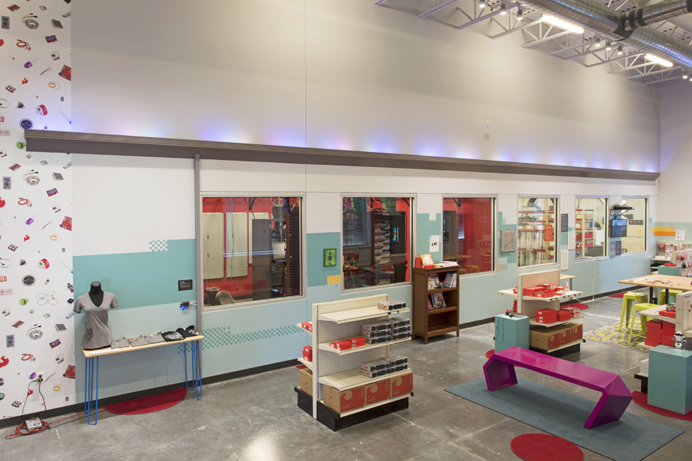
While designing the layout for the new SparkFun Emporium, I was given the opportunity to design a large LED art installation. I've helped build LED installations before, but had never had the opportunity to design one from the ground up. Thus was born the CandyBar, a 46-foot LED bar consisting of 8 meters of addressable LED strips (480 LEDs total), all controlled via a FadeCandy connected to a Raspberry Pi running the FadeCandy server.
Covered in this Tutorial
Controlling LEDs is one of the most fundamental tasks in embedded electronics, and it's often the "Hello World" for many beginners starting out on a new platform. However, LED-based projects add up quickly and can become complex very fast. This tutorial is intended to be a guideline for helping you design and build your own large-scale LED installation, while sharing some of the lessons learned from this build.
We'll go over the planning stage, pointing out considerations that will need to be taken as you design. This section will cover how you plan to control the LEDs, as well as power considerations. Next, we'll cover the build process. This section will cover how to build in stages for large projects, and how to make your installation transportable if need be. Last, we'll show the installation process and discuss the next steps to make your installation interactive.
Materials Used
Here is a list of all the SparkFun parts used in this project.
Other parts used in this build include:
- 24V/250W Power Supply
- OctoController and Dual Driver PCBs - Custom PCBs designed for LED installations (more info on these below).
- OctoController parts
- DualDriver parts
- Coilcraft Inductor for each DualDriver board.
- Ethernet cables of varying length. I used a 3ft. cable from SparkFun, and 15ft., 25ft., and 50ft. cables from Amazon.
No two installations will ever be exactly the same. This list is just here for reference and suggestions. Your vision and budget may vary, resulting in certain parts being added or omitted.
Suggested Reading
The FadeCandy GitHub is definitely the place to start if you've opted to use the FadeCandy in your project. There are tons and tons of examples showing how to control it through various means, from C++ and Python code to Processing.
A lot was learned from my friend Dan Julio, who built a very impressive LED installation, Luminescence, for The Dairy Center in Boulder, CO. His controller and driver PCBs were used in this design to ensure the installation would be robust and last as long as the space it's housed within. More information about these boards can be found on his website.
This FadeCandy LED Curtain tutorial written by Phillip Burgess was also very helpful. Learning how to set up the FadeCandy Server with multiple FadeCandy devices or with an irregular number of LEDs requires altering the configuration file for the server. This tutorial helps clarify how to setup said configuration as well as offering lots of other great tips.
If you need to brush up on some more basic concepts, here are some that pertain to this tutorial.
- Ohm's Law & Electric Power - Together, these tutorials teach you how to calculate all the necessary power requirements your LEDs will require.
- LED Basics - Learn about the finer details pertaining to light-emitting diodes.
- How to Solder - There's lots to solder in any installation.
- Working with Wire - Being a pro at wire splicing and soldering will make the build process much easier.
- Getting Started with Raspberry Pi - If you've never worked with the Pi or similar Single Board Computer before, you may want to check this out.
Planning and Design Phase
The planning and design phase is by far the most important. A well-planned project usually results in an easier build process and execution. Here are some of the considerations you'll need to make as you plan out your installation:
Addressable or Non-Addressable LEDs
This should be one of the first things you nail down. Led strips typically come in two flavors: addressable or non-addressable. Addressable LED strips, such as this one, are usually the go-to for many art installations. Each individual LED on the strip can be controlled independently of one another via a small microcontroller attached to each LED. Any installation you've seen that is displaying images or patterns is most likely using addressable LEDs. The project covered in this guide uses addressable LEDs.
In contrast, there are non-addressable LED strips. These strips are generally cheaper, but they offer much less control. The entire strip can either be on or off, there is no individual LED control, and the entire strip can only be one color at a time. For installations that don't require the display of many different colors at once, this may be a better option. You could also use a number of these strips and control each strip independently, which would still give you many colors in one area.
Before diving in to the build, it's a good idea to test each strip individually to avoid complicated troubleshooting down the road. Also worth noting is that these strips can come in different densities, as in amount of LEDs per strip. Be aware of whether you're using strips with 60 LEDs per meter versus 64 LEDs per meter. This will come into play later on.
Controlling the LEDs and Hardware Limitations
If you want to get really crazy, hackaday demonstrates how to power 1000 NeoPixels with the Arduino’s limited RAM.
Or you can try to adapt the example code to your favorite microcontroller. Teensy development boards are an excellent choice when using a large number of WS2812 LEDs.
How do you want to control all these LEDs? One of the biggest factors when deciding this is figuring out how many LEDs you want your final installation to contain. Some LED controllers have limitations on how many LEDs they can control. For example, the FadeCandy can handle up to 512 LEDs each. If you have more than 512 LEDs, you'll need to add a second FadeCandy or use a different driver. More drivers means an added bit of complexity, as you'll need to keep track of the addresses of each one, as well as each LED's location.
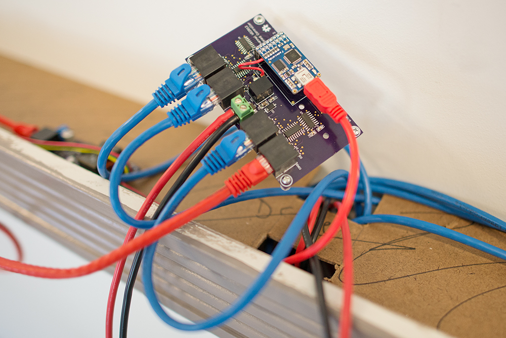
Only one FadeCandy was used to control the 480 LEDs in the CandyBar. It lives atop the OctoController board from danjuliodesigns.com, and communicates to the Driver boards over varying lengths of Ethernet cables. The Ethernet cables provide both power and communication to each pair of LED strips through the DualDriver boards as well as ESD protection.
Power
This is one area that is often overlooked. A few LEDs draw very little power, but add up several hundred and you have one very power-hungry project. Not only that, but power must be distributed evenly to prevent some LEDs appearing brighter than others or putting off slightly different colors.
For the CandyBar, the same power scheme that Dan used in his Luminescence project was used, scaled for my purposes: a single 24V/250W power supply, which then delivers 5V to each subsequent DualDriver board at up to 30 Watts per pair of LED strips (2x1 meter segments).
If you want to add more LEDs, you will need to add more power. Dan ended up using five of these supplies to power, one for each of the five FadeCandies controlling the 2300 LEDs in the sculpture.

You're not limited to these particular power supplies. If you have high-current 5V supplies, you can power the strips directly from them. Just be aware of how much current you're drawing from any power supply you use.
Space and Environmental Conditions
How are you going to enclose this project? Is it going to be indoors or outdoors? Does it need to be sealed off from the elements? The answers to these questions can greatly affect how you build your project. If the LEDs need to be sealed up, heat may become an issue. If you're working indoors, you can save some money by not having to buy tons of weather proofing materials, or products that are already weatherproof.
Luckily for me, the location for the CandyBar had already been picked, and the idea to house the LEDs atop a long ledge covered in decorative molding had been decided before I was brought on to the project. Sometimes it's easier to design around a set of requirements rather than having free range to design as you see fit.
The CandyBar was built in pieces that could all be disassembled and reassembled atop the ledge. The plan was to use strips of hardboard cut into 8-foot segments. Hardboard is sturdy enough to house LED strips, but lightweight enough that it wouldn't put strain on the ledge.
I had 8 meters of LED strips to cover the 46-foot ledge. Adding more LEDs meant more power and another FadeCandy, but I wanted to keep this as simple as possible. I didn't have time to shop for different strips that have the LEDs more widely spaced apart, so I cut the strips into smaller sizes to even out the spacing between sections of LEDs. Each strip ended up getting cut in two, giving me 16 half-meter strips, and making the gaps between each much less noticeable.
As you're designing, just know that things may look good on paper, but you may have to improvise come build time.
Construction
It's wise not to start building until you have all the parts you think you'll need. As you build, you may find a need for parts you didn't think of during the design phase. Or, as in my case, you may find that you didn't get enough of a particular material.
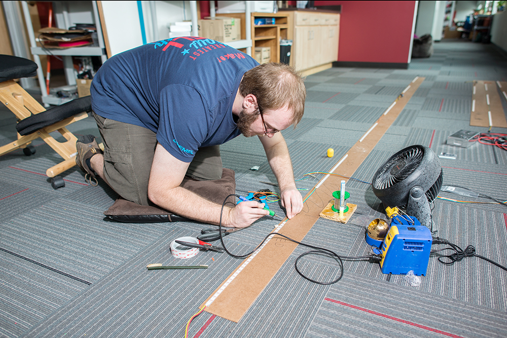
The actual assembly and construction is my favorite part. It's very satisfying to watch your project come to life, piece by piece. In my case, I needed a very long space to work in. All the pieces of hardboard were placed in one long row, just as they would be in the final installment.
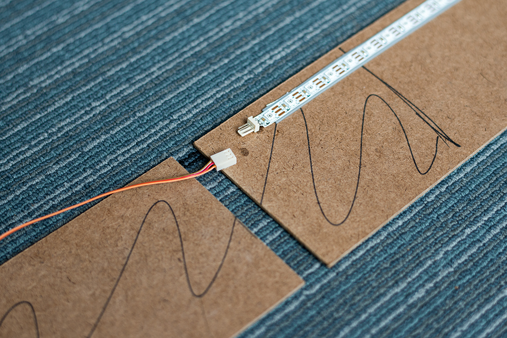
Each segment was marked where the LEDs would be attached and where the driver boards would go.
To attach the strips to the driver boards, the opposite ends of the strip that weren't needed were cut off and connected via screw terminals.

As planned, some of these connectors ended up near the end of the hardboard sections, making connecting and disconnecting a breeze. However, some of the segments did not line up with the hardboard. These strip segments were affixed with polarized connectors.
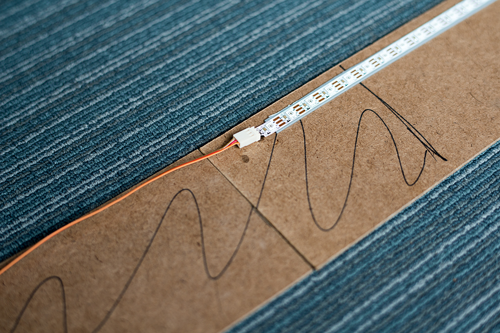
With everything marked and the LED strips prepped, it was time to adhere the strips and drivers to the hardboard with double-sided tape. Ribbon cable was used to connect the portions of LEDs that didn't need to be disassembled.
Once everything was soldered, it was time to test it all out. The FadeCandy server has a nice button to turn all the LEDs on or off for a quick test. With the solder connections all tested, the next task was to figure out the LED mapping.
Setting Up the FadeCandy Server
If you've opted to use the FadeCandy, this is a good time to set up the control portion of the project and begin testing your LED strips. This tutorial assumes that you already have you Pi set up and can ssh into it or have it attached to a monitor, keyboard and mouse.
Inside the examples folder of the FadeCandy GitHub, you'll find a config folder that houses a few different config files for the server. With help from this tutorial, the file below was created for mapping the layout of the CandyBar, which required accounting for the 60 LEDs per strip version I have, versus the 64 LEDs per strips that are set as the default in the file.
{
    "listen": [null, 7890],
    "verbose": true,

    "color": {
        "gamma": 2.5,
        "whitepoint": [1.0, 1.0, 1.0]
    },

    "devices": [
        {
            "type": "fadecandy",
            "map": [
                [ 0,    0,   0, 60 ],
                [ 0,   60,  64, 60 ],
                [ 0,  120, 128, 60 ],
                [ 0,  180, 192, 60 ],
                [ 0,  240, 256, 60 ],
                [ 0,  300, 320, 60 ],
                [ 0,  360, 384, 60 ],
                [ 0,  420, 448, 60 ]
            ]
        }
    ]
}
Another gotcha is that the mapping assumes you are creating an array of LED strips, like a display, and the CandyBar is just a line of LEDs. Thus every other strip was mapped backward, with strip one mapping from 0-59, and the following going from 119-60. You can account for this in software or in the server config file should your project also be linear in design. I ended up just accounting for it in software. The Python sketch below was great for a quick test.
language:python
#!/usr/bin/env python

# Light each LED in sequence, and repeat.

import opc, time

numLEDs = 480
client = opc.Client('fadecandy.local:7890')

while True:
    for i in range(59, 0, -1):
        pixels = [ (0,0,0) ] * numLEDs
        pixels[i] = (255, 255, 255)
        client.put_pixels(pixels)
        time.sleep(0.01)
    for i in range(60, 119):
        pixels = [ (0,0,0) ] * numLEDs
        pixels[i] = (255, 255, 255)
        client.put_pixels(pixels)
        time.sleep(0.01)
    for i in range(179, 120, -1):
        pixels = [ (0,0,0) ] * numLEDs
        pixels[i] = (255, 255, 255)
        client.put_pixels(pixels)
        time.sleep(0.01)
    for i in range(180, 239):
        pixels = [ (0,0,0) ] * numLEDs
        pixels[i] = (255, 255, 255)
        client.put_pixels(pixels)
        time.sleep(0.01)
    for i in range(299, 240, -1):
        pixels = [ (0,0,0) ] * numLEDs
        pixels[i] = (255, 255, 255)
        client.put_pixels(pixels)
        time.sleep(0.01)
    for i in range(300, 359):
        pixels = [ (0,0,0) ] * numLEDs
        pixels[i] = (255, 255, 255)
        client.put_pixels(pixels)
        time.sleep(0.01)
    for i in range(419, 360, -1):
        pixels = [ (0,0,0) ] * numLEDs
        pixels[i] = (255, 255, 255)
        client.put_pixels(pixels)
        time.sleep(0.01)
    for i in range(420, 479):
        pixels = [ (0,0,0) ] * numLEDs
        pixels[i] = (255, 255, 255)
        client.put_pixels(pixels)
        time.sleep(0.01)
Installation
Once you have all the bits and pieces assembled, it's time to install them in their permanent (or temporary) resting place. A word of advice: high-up, long installations can be a pain to troubleshoot.

Each driver is connected and tested after installation.
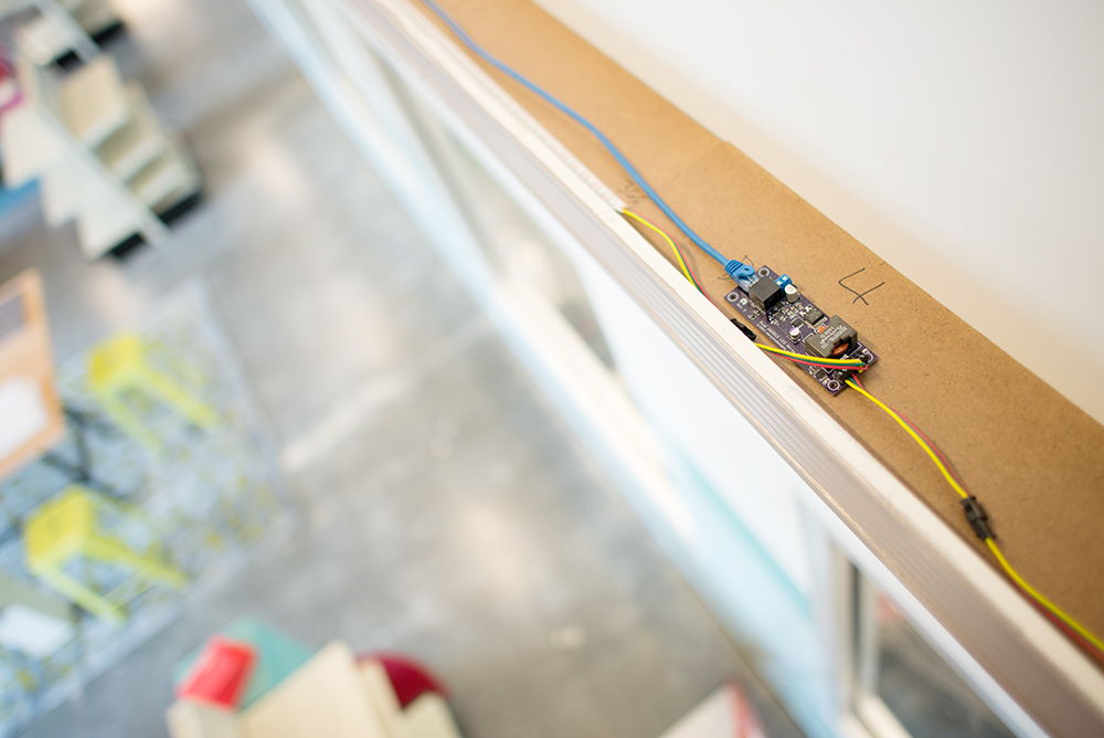
Each cable runs back to the controller board.
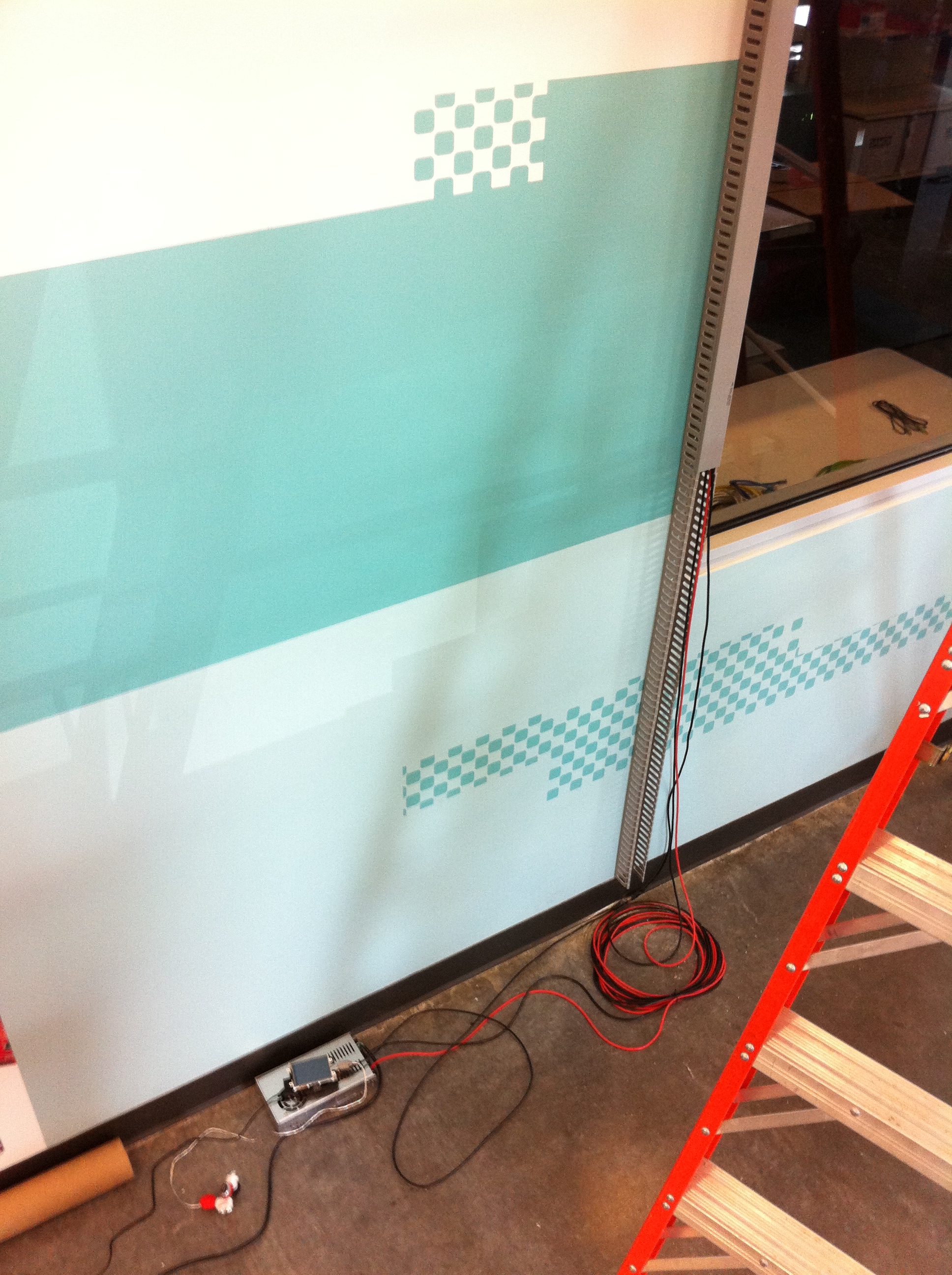
Power cables and an extra long mini-USB cable from the FadeCandy run from the controller board through the ledge, through a wall-mounted cable keeper and attach to the Raspberry Pi and power supply.
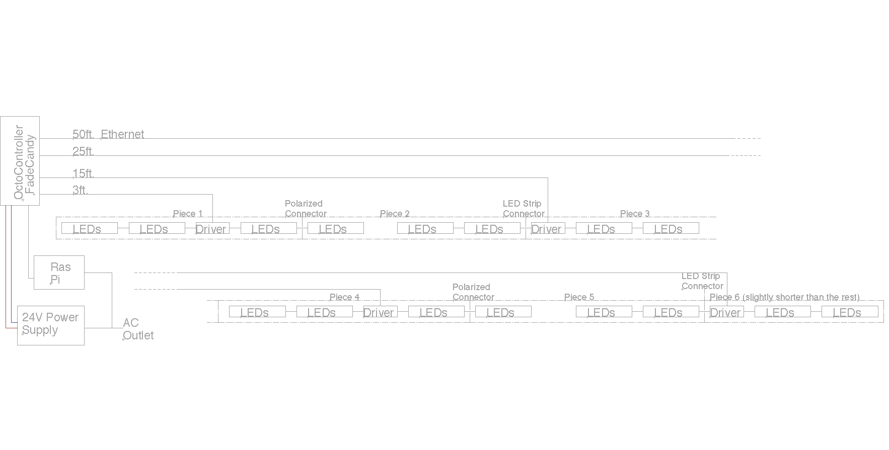
Here's a block diagram that shows what all the connections look like.
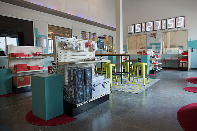
Once you have everything installed, it's time to fire it up, and bask in the warming glow of your art.
Resources and Going Further
I hope this tutorial has given you some ideas for how to take on the task of building a large installation. There are numerous ways to make such an installation interactive, and with the FadeCandy, the control possibilities are seemingly endless. I've thought of using accelerometers and/or force sensors to make an LED combat game, à la Dragon Ball. I also intend to make an LED cube, similar to ones I've made in the past, that can control the color or patterns of the bar.
If you'd like to learn more about the FadeCandy, check out the links below.
- FadeCandy GitHub - This repo seriously has a ton of examples and info if you check all the read me's.
- Udder - Udder is a lighting control server by Mike Bissell that drives the Fade Candy servers with complex, never repeating patterns.
- Open Pixel Control (OPC) - OPC is the protocol used to communicate to the FadeCandy in many examples.
For more large art inspiration, check out these tutorials: