Blynk Board Bridge Widget Demo
 .Brent.
Mobile Apps
To create a mobile app, first make sure you have the Blynk app installed. If you don't, please install the version for your OS from one of these two sources:


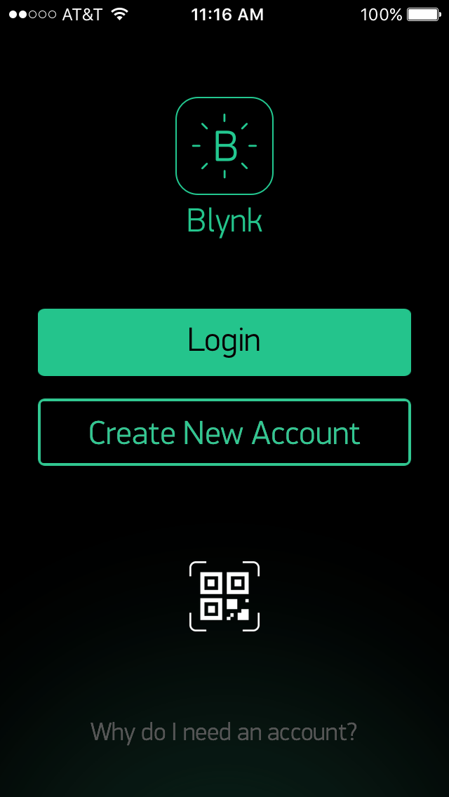
Exact instructions are beyond the scope of this tutorial. Visit the Getting Started with Blynk Guide, if you have not done so already. Once you have the app installed, login, or create a new account.
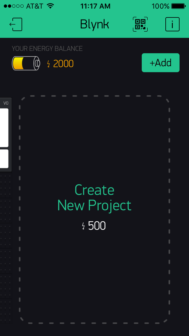
Once you have logged in, select the large Create New Project button.
This will bring you to where you name the project. Select the hardware that you will be connecting to, and get your authentication token. This token (7DF0F1DE119F48149EFF64BC7B2FBD11 in this example) will be very important later. I find that emailing it to myself is easier than typing it out. It will be sent to the email account that you registered with when you created your account.
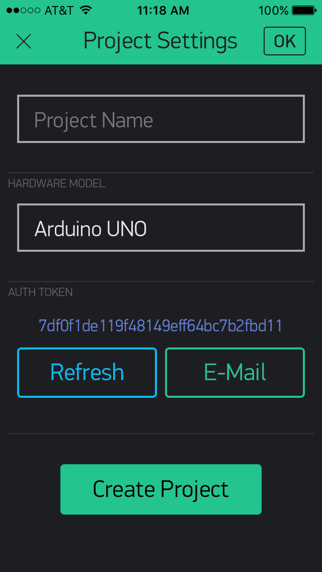
I gave my project a name that matches the sketch designed to work with it. This is unnecessary, but helps keep confusion to a minimum. Once you select some SparkFun hardware, note that the theme changes.
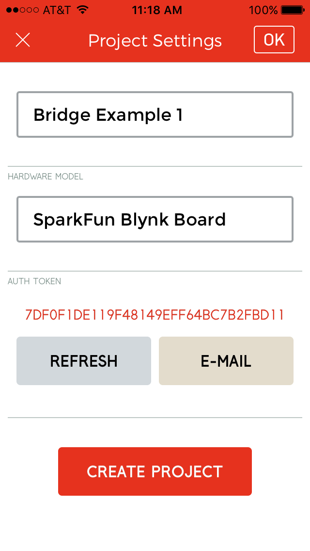
Select the CREATE PROJECT option to create and open the project.
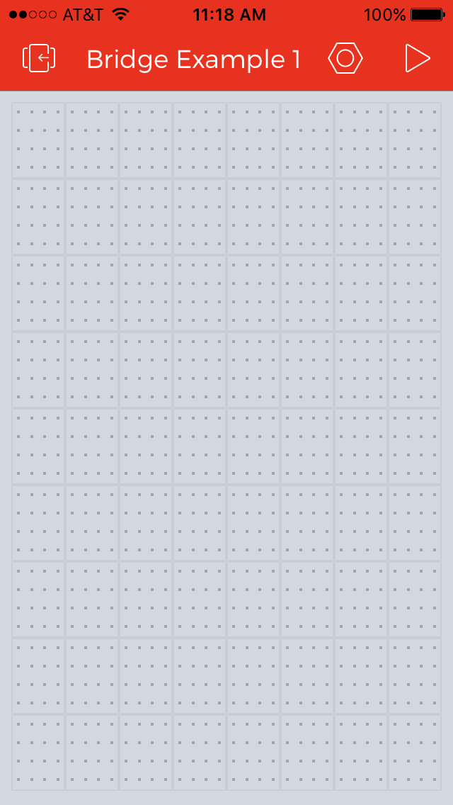
Now that you have an empty project canvas to work with, it's time to start adding UI elements. Let's start with the Terminal widget. You find this by double tapping the canvas and scrolling the sidebar until you see the widget of interest.
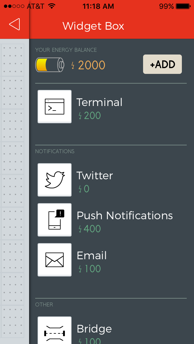
Select the widget, and the Widget Box will close. The selected widget will appear in the next available slot on the canvas.
Now that you have a terminal widget in place, find the button widget in the Widget Box.
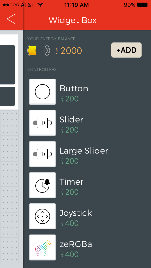
Follow the same procedure to place the Bridge widget. It can be found in the other section of the Widget Box at the bottom.
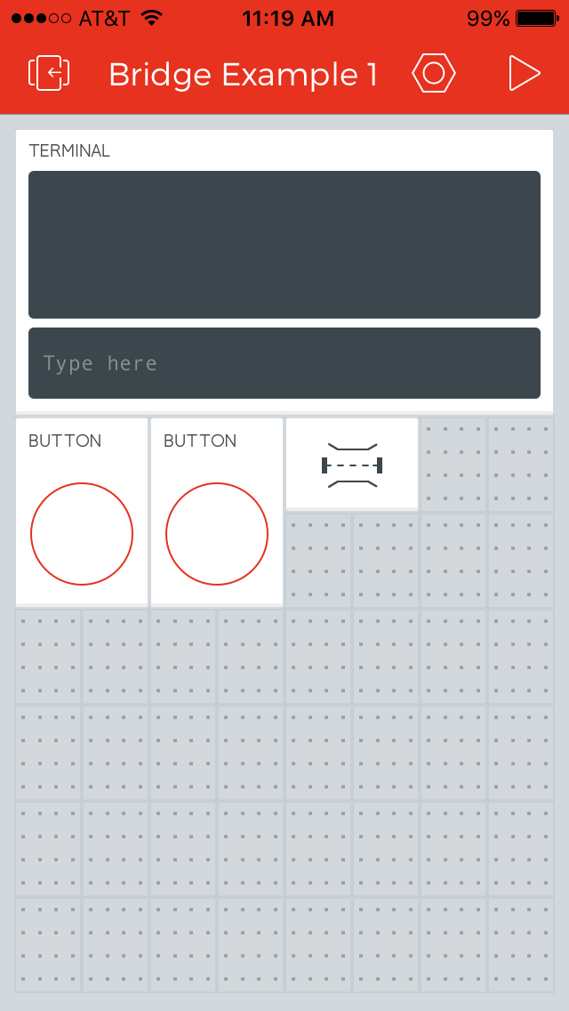
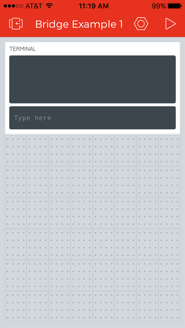
Once all of the widgets are placed, it's time to configure them. Start by configuring the Terminal widget. Give it a name/label. It doesn't matter what case you enter, it will be converted to upper CASE.
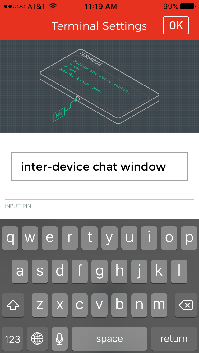
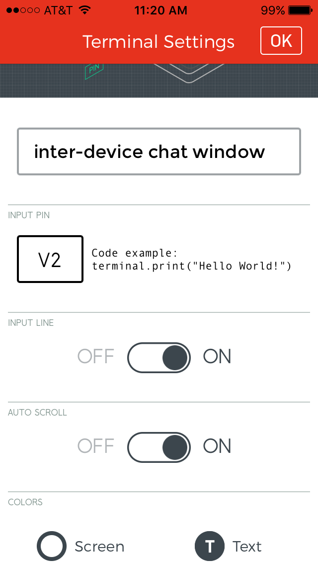
In order to interact with a widget, you need to assign a pin to it. Some widgets use real, physical pins, while others use virtual pins. All of the UI in this example uses virtual pins. In this case, I've chosen to connect the terminal to virtual pin 0. I left the other settings for the Terminal widget at their default values.
The procedure is the same for the Button widgets as it is for the Termial widget. Give them names/labels, and select a pin to communicate through. I think case I'm using virtual pin zero to control the local LED connected to GP5. The reason for using a virtual pin rather than a physical pin will be explained in the firmware section.
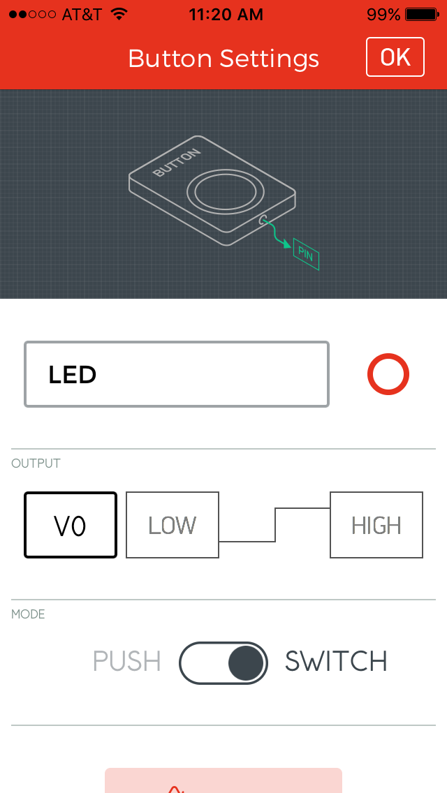
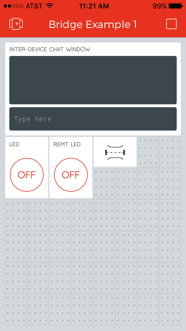
Note that in the image above, I've also changed the button from PUSH (momentary) to SWITCH (latching). The other configuration options for Button widgets control to color. That wasn't important to this demo, and I left the defaults. Here is what the finished app should look like:
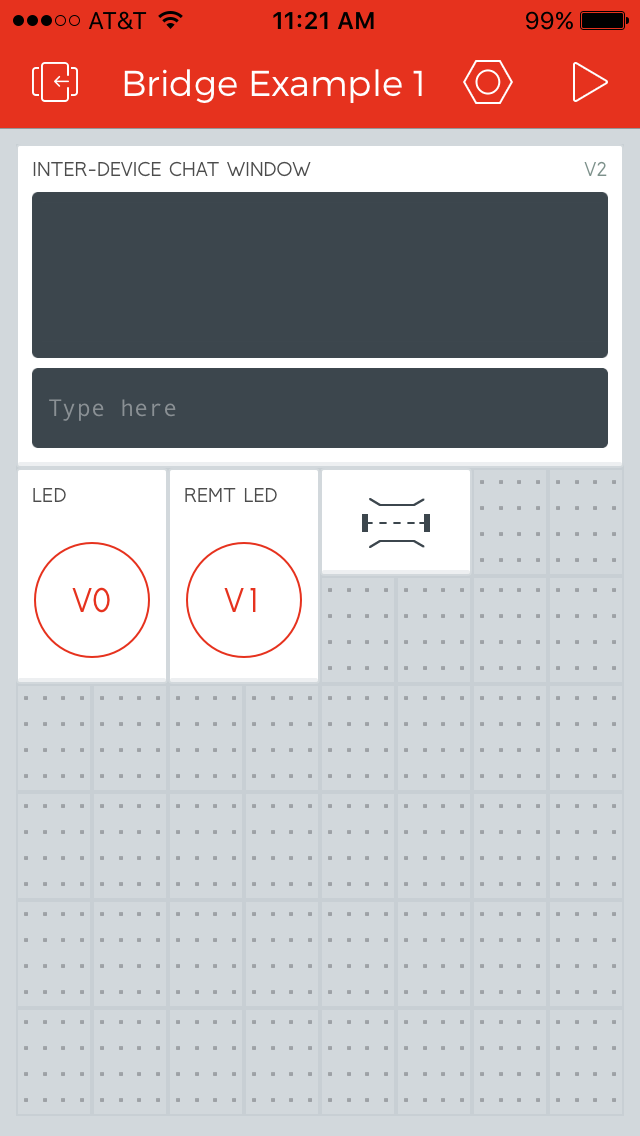
When the triangle in the upper-right corner is pressed, the app will run, and the details of the wiring are hidden from the user.