BlackBerry Trackballer Breakout Hookup Guide
This Tutorial is Retired!
This tutorial covers concepts or technologies that are no longer current. It's still here for you to read and enjoy, but may not be as useful as our newest tutorials.
 Toni_K
Hardware Overview
There are five main features to the breakout board of which the user should be aware.
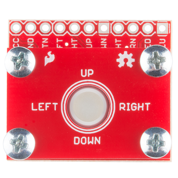
Trackball
The BlackBerry trackball is the main feature of this board. Four tiny spindles on the trackball each have small magnets on their ends. These each trigger a paired SMD hall effect sensor, giving the user the ability to track up, down, left, and right movement of the trackball.
The four directions can be tracked as outputs on the header pins labeled LFT, RHT, UP, and DWN.
Pushbutton
Underneath the trackball, there is a small SMD momentary switch. This allows the user to trigger events or make selections with a simple 'click'.
This output is broken out to the header pin labeled BTN.
LEDs
Additionally, underneath the trackball are four LEDs. The LED colors include:
- White
- Red
- Green
- Blue
These LEDs can light up the clear trackball any color desired by the user. Combinations of the four LEDs lit up can also be used to customize the trackball color.
Each LED is broken out to its own header pin. The header pins are labeled WHT, GRN, RED, and BLU.
Power Connection
In order to properly run the hall effect sensors, momentary switch, and LEDs, the user must supply power on two headers broken out, labeled VCC and GND. Power supplied to the board should be regulated, but can be anywhere from 2.5-5.25V.
Mounting PCB
The final feature of the breakout is the mounting PCB, included to mechanically stabilize the trackball. It is mounted to the breakout board using four Phillips 4-40 screws and four nylon 4-40 standoffs. This PCB is included to prevent the trackball from being ripped off of the breakout board.
This mounting board can be replaced with other types of mechanical stabilization provided by the user. For example, if the trackballer breakout is mounted into a project enclosure, the top mounting PCB may be removed.