BlackBerry Trackballer Breakout Hookup Guide
This Tutorial is Retired!
This tutorial covers concepts or technologies that are no longer current. It's still here for you to read and enjoy, but may not be as useful as our newest tutorials.
 Toni_K
Hardware Hookup
Now that you are familiar with the Trackballer Breakout board, it's time to hook everything up!
Solder Headers
We recommend using right angle headers to solder to the standard 0.1" breakout pins. This will allow you to easily read the header labels without jumper wires in the way. However, you could also solder bare wires directly to the PCB if you wish. If you're unsure how to do this, please check out our tutorial here.
Pin Connections
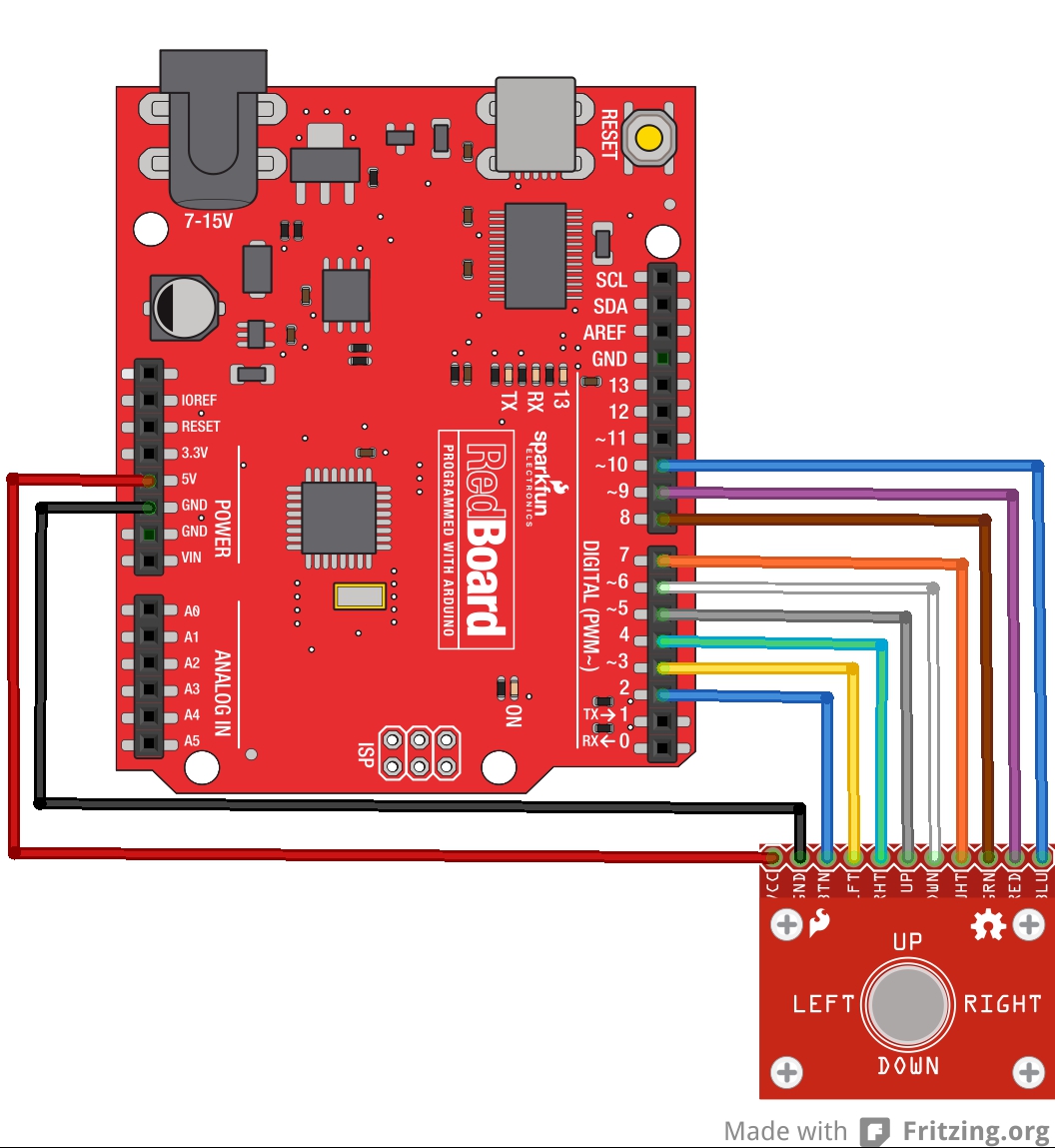
Once headers are soldered on the board, you can now use jumper wires to connect the trackball breakout to the RedBoard. Use the following connections.
Trackballer Breakout → RedBoard
- VCC → 5V
- GND → GND
- BTN → D2
- LFT → D3
- RHT → D4
- UP → D5
- DWN → D6
- WHT → D7
- GRN → D8
- RED → D9
- BLU → D10
Final Circuit
Once everything is connected, your circuit should look like the following diagram: