BlackBerry Trackballer Breakout Hookup Guide
This Tutorial is Retired!
This tutorial covers concepts or technologies that are no longer current. It's still here for you to read and enjoy, but may not be as useful as our newest tutorials.
 Toni_K
Arduino Code
Once the circuit is hooked up properly, it's time to upload code to the RedBoard and start playing with the trackballer.
If you are unfamiliar with how to use the Arduino IDE, please check out our tutorial here.
First, download the demo sketch, and open it up in your Arduino IDE.
You can also download the most up-to-date code from the GitHub repo.
Make sure to select Uno in the board drop-down menu, and select the correct COM port for your RedBoard. Upload the code.
With the code uploaded, open up your favorite serial port monitor. Use the settings 9600bps, 8, N, 1. If you are unsure how to do this, check out our Serial Terminal Basics tutorial.
Let's take a look at what the code does. In the first section, we are declaring pin connections between the trackballer and the RedBoard. This includes the four trackball pins, the button, and the LEDs. We also declare our variables we will be using later in the sketch.
language:c
//Define Trackballer Breakout pin connections to Arduino
#define Btn 2
#define Lft 3
#define Rht 4
#define Up 5
#define Dwn 6
#define WHT_LED 7
#define GRN_LED 8
#define RED_LED 9
#define BLU_LED 10

//Define variables used in sketch
int buttonClick;
unsigned long mouse_Lft;
unsigned long mouse_Rht;
unsigned long mouse_Up;
unsigned long mouse_Dwn;
int x_position;
int y_position;
The setup loop is where we tell the RedBoard what to do with all those pins we just defined. First, we set all of the trackball pins and button pins as inputs (the RedBoard will be receiving information from these pins). We then declare the LED pins as outputs (the RedBoard will be controlling these pins).
We begin our serial port at 9600bps, and begin cycling through turning on each of the LEDs, one at a time. Each LED remains on for one second, then turns off. Once all the LEDs have been cycled, we move on to the main loop where the trackball shows its capabilities.
language:c
/*********************Setup Loop*************************/
void setup() {

  //Define pin functionality on the Arduino
  pinMode(Btn, INPUT);
  pinMode(Lft, INPUT);
  pinMode(Rht, INPUT);
  pinMode(Up, INPUT);
  pinMode(Dwn, INPUT);
  pinMode(WHT_LED, OUTPUT);
  pinMode(GRN_LED, OUTPUT);
  pinMode(RED_LED, OUTPUT);
  pinMode(BLU_LED, OUTPUT);

  //Pull LED pins low to prevent flickering
  digitalWrite(WHT_LED, LOW);
  digitalWrite(GRN_LED, LOW);
  digitalWrite(RED_LED, LOW);
  digitalWrite(BLU_LED, LOW);

  //Start Serial port for debugging.
  Serial.begin(9600);
  Serial.println("Begin Trackballer Demo");

  //Demo each LED by turning them on individually for one second.
  Serial.println("Turn on LEDs individually");
  digitalWrite(WHT_LED, HIGH);
  delay(1000);
  digitalWrite(WHT_LED, LOW);

  digitalWrite(GRN_LED, HIGH);
  delay(1000);
  digitalWrite(GRN_LED, LOW);

  digitalWrite(RED_LED, HIGH);
  delay(1000);
  digitalWrite(RED_LED, LOW);

  digitalWrite(BLU_LED, HIGH);
  delay(1000);
  digitalWrite(BLU_LED, LOW);

  Serial.println("Begin Trackball tracking");
}
When the main loop begins, the RedBoad will be waiting for input from the trackball, and will output a coordinate to the serial monitor. The RedBoard first polls each of the trackball pins. The function pulseIn waits for up to 20000 microseconds to determine if there is any pulse (the pin driving HIGH) coming in from the trackballer. If so, the pulse length (again, in microseconds) is recorded to the variable name, and the RedBoard moves on to the next pin. If no pulse comes in, the variable is assigned the value of 0. You can find more information on this function here.
language:c
/*********************Main Loop*************************/
void loop() {

  //Wait for 2ms on each direction pin for movement.
  //Pins are driven HIGH by the breakout board.
  //pulseIn measures the length of each pulse in microseconds.
  mouse_Lft = pulseIn(Lft, HIGH, 20000);
  mouse_Rht = pulseIn(Rht, HIGH, 20000);
  mouse_Up = pulseIn(Up, HIGH, 20000);
  mouse_Dwn = pulseIn(Dwn, HIGH, 20000);
Once the variables have been written, the RedBoard then compares each value to determine if there was any pulse input. In our case, we simply want to see any movement, so we compare to a time of 0 seconds. If you want to only register long scrolls, you can increase the value being compared. If pulses were recorded, we adjust the x- and y-coordinates accordingly. Since we are basing this off of a Cartesian coordinate system, we record Up and Right movement as positive incrementations, while Down and Left movements are negative incrementations.
These coordinates are then printed to the Serial monitor.
language:c
  //Determine if there was movement in any direction.
  //If movement occurred, adjust x/y coordinates based on movements.
  //Directionality is based off of an x/y plane (i.e., Up 1 unit and Right 1 unit = (1,1))
  if (mouse_Lft > 0)
  {
    x_position= --x_position;
  }
  if (mouse_Rht > 0)
  {
    x_position= ++x_position;
  }
  if (mouse_Up > 0)
  {
    y_position= ++y_position;
  }
  if (mouse_Dwn > 0)
  {
    y_position= --y_position;
  }

  //Output x/y coordinates to Serial terminal
  Serial.print("Trackball Position: \t X-Position= ");
  Serial.print(x_position);
  Serial.print(" \t Y-position= ");
  Serial.print(y_position);
  Serial.println();
Finally, we check for any button clicks. If the RedBoard reads the button pin as LOW, the button has been clicked, and this is output to the Serial terminal.
language:c
  //Check for button click. If present, print to Serial monitor.
  buttonClick = digitalRead(Btn);
  if (buttonClick == LOW)
  {
    Serial.println("Click");
  }
}
If your trackballer is hooked up correctly and your RedBoard has been programmed without issue, you should see the following output on your terminal monitor. Try scrolling the trackball and clicking the button to verify everything is working correctly. The trackball position counter will increment up or down, depending on how you roll the ball.
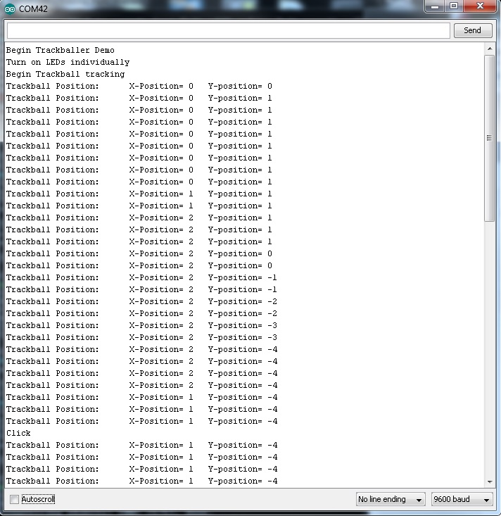
In this example, I rolled the trackball up and to the right. I then rolled it down several times and to the left. You can see when I clicked the push button towards the bottom.