BlackBerry Trackballer Breakout Hookup Guide
This Tutorial is Retired!
This tutorial covers concepts or technologies that are no longer current. It's still here for you to read and enjoy, but may not be as useful as our newest tutorials.
 Toni_K
Introduction
The SparkFun BlackBerry Trackballer Breakout gives the user easy access to a trackball which measures up, down, left, and right movements, as well as clicks on the board. It also adds a bit of flair to your project with 4 LEDs.
SparkFun Blackberry Trackballer Breakout
COM-13169Materials Required
We recommend the following products to follow along with this hookup guide.
Suggested Reading
If you aren't familiar with the following concepts, we recommend reviewing them before beginning to work with the BlackBerry Trackballer Breakout.
How to Solder: Through-Hole Soldering
How to Power a Project
Working with Wire
Installing Arduino IDE
Button and Switch Basics
Light-Emitting Diodes (LEDs)
Analog vs. Digital
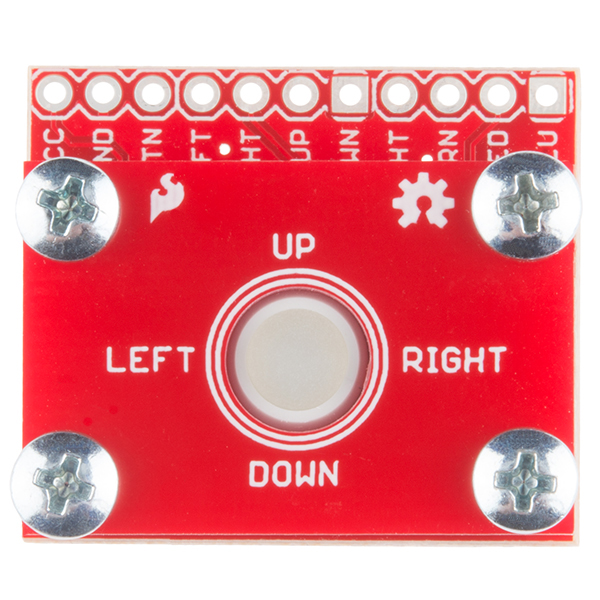
Hardware Overview
There are five main features to the breakout board of which the user should be aware.
Trackball
The BlackBerry trackball is the main feature of this board. Four tiny spindles on the trackball each have small magnets on their ends. These each trigger a paired SMD hall effect sensor, giving the user the ability to track up, down, left, and right movement of the trackball.
The four directions can be tracked as outputs on the header pins labeled LFT, RHT, UP, and DWN.
Pushbutton
Underneath the trackball, there is a small SMD momentary switch. This allows the user to trigger events or make selections with a simple 'click'.
This output is broken out to the header pin labeled BTN.
LEDs
Additionally, underneath the trackball are four LEDs. The LED colors include:
- White
- Red
- Green
- Blue
These LEDs can light up the clear trackball any color desired by the user. Combinations of the four LEDs lit up can also be used to customize the trackball color.
Each LED is broken out to its own header pin. The header pins are labeled WHT, GRN, RED, and BLU.
Power Connection
In order to properly run the hall effect sensors, momentary switch, and LEDs, the user must supply power on two headers broken out, labeled VCC and GND. Power supplied to the board should be regulated, but can be anywhere from 2.5-5.25V.
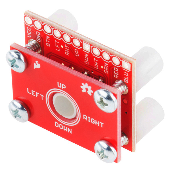
Mounting PCB
The final feature of the breakout is the mounting PCB, included to mechanically stabilize the trackball. It is mounted to the breakout board using four Phillips 4-40 screws and four nylon 4-40 standoffs. This PCB is included to prevent the trackball from being ripped off of the breakout board.
This mounting board can be replaced with other types of mechanical stabilization provided by the user. For example, if the trackballer breakout is mounted into a project enclosure, the top mounting PCB may be removed.
Hardware Hookup
Now that you are familiar with the Trackballer Breakout board, it's time to hook everything up!
Solder Headers
We recommend using right angle headers to solder to the standard 0.1" breakout pins. This will allow you to easily read the header labels without jumper wires in the way. However, you could also solder bare wires directly to the PCB if you wish. If you're unsure how to do this, please check out our tutorial here.
Pin Connections
Once headers are soldered on the board, you can now use jumper wires to connect the trackball breakout to the RedBoard. Use the following connections.
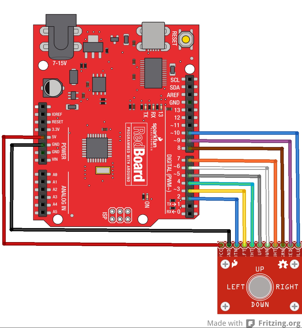
Trackballer Breakout → RedBoard
- VCC → 5V
- GND → GND
- BTN → D2
- LFT → D3
- RHT → D4
- UP → D5
- DWN → D6
- WHT → D7
- GRN → D8
- RED → D9
- BLU → D10
Final Circuit
Once everything is connected, your circuit should look like the following diagram:
Arduino Code
Once the circuit is hooked up properly, it's time to upload code to the RedBoard and start playing with the trackballer.
If you are unfamiliar with how to use the Arduino IDE, please check out our tutorial here.
First, download the demo sketch, and open it up in your Arduino IDE.
You can also download the most up-to-date code from the GitHub repo.
Make sure to select Uno in the board drop-down menu, and select the correct COM port for your RedBoard. Upload the code.
With the code uploaded, open up your favorite serial port monitor. Use the settings 9600bps, 8, N, 1. If you are unsure how to do this, check out our Serial Terminal Basics tutorial.
Let's take a look at what the code does. In the first section, we are declaring pin connections between the trackballer and the RedBoard. This includes the four trackball pins, the button, and the LEDs. We also declare our variables we will be using later in the sketch.
language:c
//Define Trackballer Breakout pin connections to Arduino
#define Btn 2
#define Lft 3
#define Rht 4
#define Up 5
#define Dwn 6
#define WHT_LED 7
#define GRN_LED 8
#define RED_LED 9
#define BLU_LED 10

//Define variables used in sketch
int buttonClick;
unsigned long mouse_Lft;
unsigned long mouse_Rht;
unsigned long mouse_Up;
unsigned long mouse_Dwn;
int x_position;
int y_position;
The setup loop is where we tell the RedBoard what to do with all those pins we just defined. First, we set all of the trackball pins and button pins as inputs (the RedBoard will be receiving information from these pins). We then declare the LED pins as outputs (the RedBoard will be controlling these pins).
We begin our serial port at 9600bps, and begin cycling through turning on each of the LEDs, one at a time. Each LED remains on for one second, then turns off. Once all the LEDs have been cycled, we move on to the main loop where the trackball shows its capabilities.
language:c
/*********************Setup Loop*************************/
void setup() {

  //Define pin functionality on the Arduino
  pinMode(Btn, INPUT);
  pinMode(Lft, INPUT);
  pinMode(Rht, INPUT);
  pinMode(Up, INPUT);
  pinMode(Dwn, INPUT);
  pinMode(WHT_LED, OUTPUT);
  pinMode(GRN_LED, OUTPUT);
  pinMode(RED_LED, OUTPUT);
  pinMode(BLU_LED, OUTPUT);

  //Pull LED pins low to prevent flickering
  digitalWrite(WHT_LED, LOW);
  digitalWrite(GRN_LED, LOW);
  digitalWrite(RED_LED, LOW);
  digitalWrite(BLU_LED, LOW);

  //Start Serial port for debugging.
  Serial.begin(9600);
  Serial.println("Begin Trackballer Demo");

  //Demo each LED by turning them on individually for one second.
  Serial.println("Turn on LEDs individually");
  digitalWrite(WHT_LED, HIGH);
  delay(1000);
  digitalWrite(WHT_LED, LOW);

  digitalWrite(GRN_LED, HIGH);
  delay(1000);
  digitalWrite(GRN_LED, LOW);

  digitalWrite(RED_LED, HIGH);
  delay(1000);
  digitalWrite(RED_LED, LOW);

  digitalWrite(BLU_LED, HIGH);
  delay(1000);
  digitalWrite(BLU_LED, LOW);

  Serial.println("Begin Trackball tracking");
}
When the main loop begins, the RedBoad will be waiting for input from the trackball, and will output a coordinate to the serial monitor. The RedBoard first polls each of the trackball pins. The function pulseIn waits for up to 20000 microseconds to determine if there is any pulse (the pin driving HIGH) coming in from the trackballer. If so, the pulse length (again, in microseconds) is recorded to the variable name, and the RedBoard moves on to the next pin. If no pulse comes in, the variable is assigned the value of 0. You can find more information on this function here.
language:c
/*********************Main Loop*************************/
void loop() {

  //Wait for 2ms on each direction pin for movement.
  //Pins are driven HIGH by the breakout board.
  //pulseIn measures the length of each pulse in microseconds.
  mouse_Lft = pulseIn(Lft, HIGH, 20000);
  mouse_Rht = pulseIn(Rht, HIGH, 20000);
  mouse_Up = pulseIn(Up, HIGH, 20000);
  mouse_Dwn = pulseIn(Dwn, HIGH, 20000);
Once the variables have been written, the RedBoard then compares each value to determine if there was any pulse input. In our case, we simply want to see any movement, so we compare to a time of 0 seconds. If you want to only register long scrolls, you can increase the value being compared. If pulses were recorded, we adjust the x- and y-coordinates accordingly. Since we are basing this off of a Cartesian coordinate system, we record Up and Right movement as positive incrementations, while Down and Left movements are negative incrementations.
These coordinates are then printed to the Serial monitor.
language:c
  //Determine if there was movement in any direction.
  //If movement occurred, adjust x/y coordinates based on movements.
  //Directionality is based off of an x/y plane (i.e., Up 1 unit and Right 1 unit = (1,1))
  if (mouse_Lft > 0)
  {
    x_position= --x_position;
  }
  if (mouse_Rht > 0)
  {
    x_position= ++x_position;
  }
  if (mouse_Up > 0)
  {
    y_position= ++y_position;
  }
  if (mouse_Dwn > 0)
  {
    y_position= --y_position;
  }

  //Output x/y coordinates to Serial terminal
  Serial.print("Trackball Position: \t X-Position= ");
  Serial.print(x_position);
  Serial.print(" \t Y-position= ");
  Serial.print(y_position);
  Serial.println();
Finally, we check for any button clicks. If the RedBoard reads the button pin as LOW, the button has been clicked, and this is output to the Serial terminal.
language:c
  //Check for button click. If present, print to Serial monitor.
  buttonClick = digitalRead(Btn);
  if (buttonClick == LOW)
  {
    Serial.println("Click");
  }
}
If your trackballer is hooked up correctly and your RedBoard has been programmed without issue, you should see the following output on your terminal monitor. Try scrolling the trackball and clicking the button to verify everything is working correctly. The trackball position counter will increment up or down, depending on how you roll the ball.
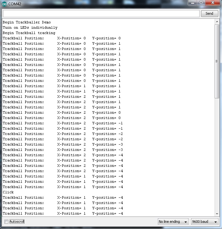
In this example, I rolled the trackball up and to the right. I then rolled it down several times and to the left. You can see when I clicked the push button towards the bottom.
Resources and Going Further
Now that you've successfully got your BlackBerry Trackballer breakout up and running, it's time to incorporate it into your own project!
For more information, check out the resources below:
- Schematic (PDF)
- Eagle Files (ZIP)
- AN4884 Datasheet (PDF) - Datasheet for the hall effect sensor
- GitHub Repo - (Library & Design Files)
- SparkFun Product Showcase: BlackBerry Trackballer breakout
Once you've successfully gotten data out from your trackballer breakout, it's time to create your own project based around the breakout board! Will you use it as a driver for a remote robot? Or perhaps an interactive art display? We want to see what you come up with! If you need some ideas to get started, try customizing the LED color of the trackball to light up when you press the button. Alternatively, try using your trackballer as a drawing tool in Processing! Need some inspiration for your next project? Check out some of these tutorials:
Connecting Arduino to Processing
HID Control of a Web Page
If you have any feedback, please visit the comments or contact our technical support team at TechSupport@sparkfun.com.