Basic Servo Control for Beginners
 El Duderino
Servo Motor Basics
Before we get to the examples in this tutorial, we'll want to review a few basics about servo motors. For a detailed rundown of servos, their background, and how they work, take a look at our Hobby Servo Tutorial.
Standard vs Continuous Servos
SparkFun carries two types of hobby servo motors: standard and continuous rotation. There are several differences between the two types but for the purpose of this tutorial we'll only review the primary distinctions between Standard and Continuous Rotation servos.
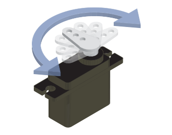
A standard servo moves on a rotation arc (usually 0-90° or 0-180°) and provides positional feedback to the controller. This lets you move it to a specific point on the rotation arc and the servo reports its position back to the controller. Standard servos work great for things like steering control in R/C applications, controlling a robotic gripper or controlling a pan/tilt bracket like we cover later in this tutorial.
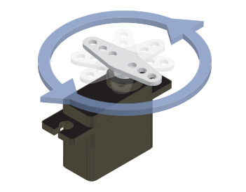
A continuous rotation servo (sometimes referred to as a full rotation or just 360° servo) behaves more like a standard DC motor. Instead of controlling the position of the servo, the controller sets the speed and direction of the motor. Continuous rotation servos work well as drive motors or other applications where you need to control the speed and direction of a motor with just a few wires.
Each type has their benefits and drawbacks so you will want to consider whichever type works best for your servo project.
Connector Pinout
One of the most important things to make note of with any servo is the pinout of the connector in order to prevent wiring things up incorrectly.
Most servos follow a specific color-code for Power (VCC), Ground (GND) and Control Signal. The table below lists the color-coding for three commonly used servo connector types. The pin numbering is almost universally the same but manufacturers may use different colors for the wires. If your servo does not match or you are not certain, it is always best to double-check the documentation for your servo.
| Pin Number & Name | Color Scheme - Hitec | Color Scheme - Futaba | Color Scheme - JR |
|---|---|---|---|
| 1. Ground (-) | Black | Black | Brown |
| 2. Power Supply (+) | Red | Red | Red |
| 3. Control Signal | Yellow or White | White | Orange |
Voltage Range and Power Supply
Next, you need to select a power supply for your servo project. Make sure the voltage provided by your power supply falls into the voltage range for your servo (commonly 4.8-6V but check the datasheet for your servo to be sure). Also, ensure your power supply can supply enough current to drive the servo. Again, the datasheet for your servo will have some helpful information to figure out the max current your servo may draw from your power supply. Usually, you can look at the stall current (if listed) in your servo's datasheet to determine the max current draw of your servo motor.
Control Signal Range
The last concept we want to revisit is a servo's control signal range. We're only going to cover the control signal range for this tutorial. For a more thorough explanation of a how a servo control signal works, check out this section of our Hobby Servo tutorial.
The primary thing to remember here is your servo's control signal pulse duration/width range. This is usually between 1 and 2 ms but can vary between manufacturers and servo types. Be sure to check your servo's specifications for the pulse range to avoid damaging the motor and gearbox. This is particularly important when you are sending PWM values from a microcontroller or single board computer like we demonstrate in the Arduino and Python sections.