AT42QT1010 Capacitive Touch Breakout Hookup Guide
This Tutorial is Retired!
This tutorial covers concepts or technologies that are no longer current. It's still here for you to read and enjoy, but may not be as useful as our newest tutorials.
View the updated tutorial: AT42QT101X Capacitive Touch Breakout Hookup Guide
 Shawn Hymel
Hardware Overview
If we look at the front of the board, we see a large, circular pad (the "electrode") and several pins. The on-board electrode will detect touches when pressed with a finger as long as the board is powered.
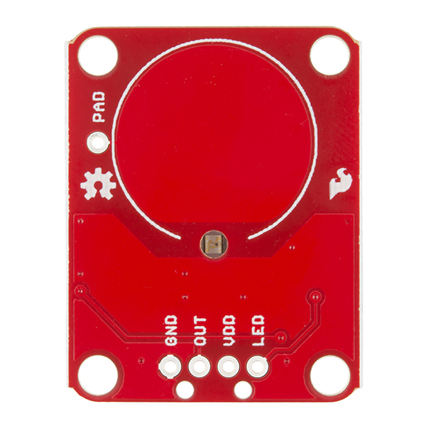
GND should be connected to the ground of the host circuit.
OUT is the output of the AT42QT1010. HIGH on touch, LOW otherwise.
VDD is the power supply for the AT42QT1010 and needs to be connected to a voltage between 1.8V - 5V.
LED controls the operation of the on-board LED. By default, it is connected to the OUT pin. If you de-solder the "LED Enable" jumper on the back side, you can independently control the LED.
PAD is located in the upper-left corner and allows you to connect to an external electrode. Note that there is a small surface mount pad on the back side by the PAD pin hole. If you want to mount the board flush, you can solder a wire directly to the surface mount pad.
How It Works
Take a look at the back side of the board.
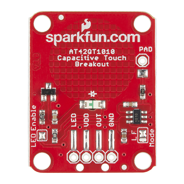
The AT42QT1010 chip is located on the right side of the board. It uses a resistor and a capacitor network to adjust the sensitivity of the electrode. High frequency pulses are sent to the pad. When a fleshy object (such as a finger) approaches the pad, it acts like a very small capacitor and changes the shape of the pulses. When the AT42QT1010 detects these slight changes, it raises the OUT line to HIGH, indicating a touch is present. Once the pulses return to normal (i.e. the fleshy object is moved away from the pad), the AT42QT1010 drives the OUT line LOW.
LED Enable
The output from the AT42QT1010 goes directly to the OUT pin on the board as well as to the transistor (left side), which operates the LED (center of board). By default, the OUT line and LED lines are connected, which means that on a touch, the on-board LED lights up. You can disconnect the LED by de-soldering the jumper labeled "LED Enable." This will cause the LED to no longer light up on a touch, but you can still drive the LED using the LED pin on the board.
Mode
On the right side of the board, you will also notice a jumper labeled "Mode" with "L" and "F" markers. By default, the center pad and the "F" pad are connected, which puts the AT42QT1010 in "Fast" mode. In Fast mode, the chip is more responsive to touch events but draws 200µA - 750µA in normal operation. If you de-solder this jumper and connect the center pad to the "L" pad, the AT42QT1010 will be in "Low Power" mode. In this mode, the chip is slightly less responsive to events but only uses 15µA - 75µA.