Assembly Guide for SparkFun JetBot AI Kit V2.0
 Evan_Double_U
1. Robotics Chassis Kit Initial Assembly
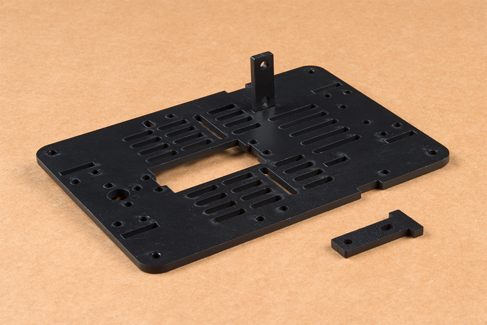
For all SparkFun Jetbot kits, begin with one of the two bare base plates included with the JetBot Chassis Kit. It does not matter which one, they are identical.
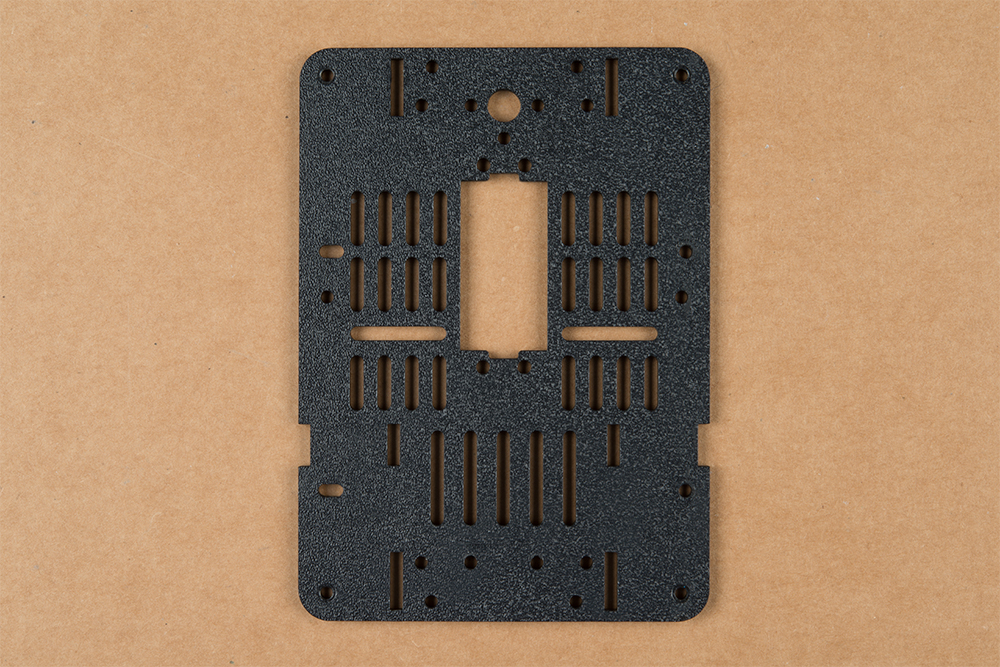
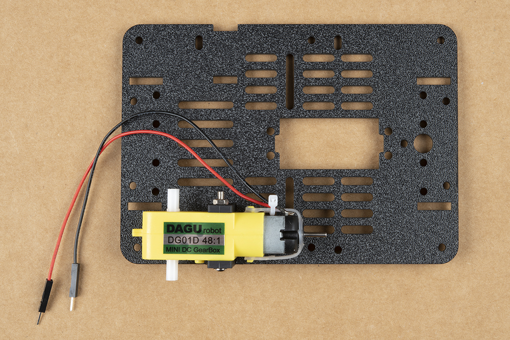
Push two of the included motor mounts through the designated holes in the base plate as shown below. Two more motor mounts will be attached on the outside of the base plate after the motor is installed.
Your JetBot Chassis Kit includes a pair of hobby motors & wheel assemblies.
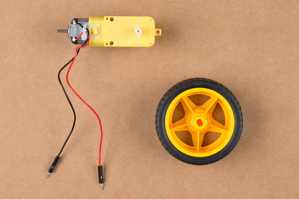
Attach the pair of motors using the long threaded machine screws & nuts included with the JetBot Chassis Kit. The motor will be sandwiched between an internal & external motor mount. Tighten the screws until they are snug.

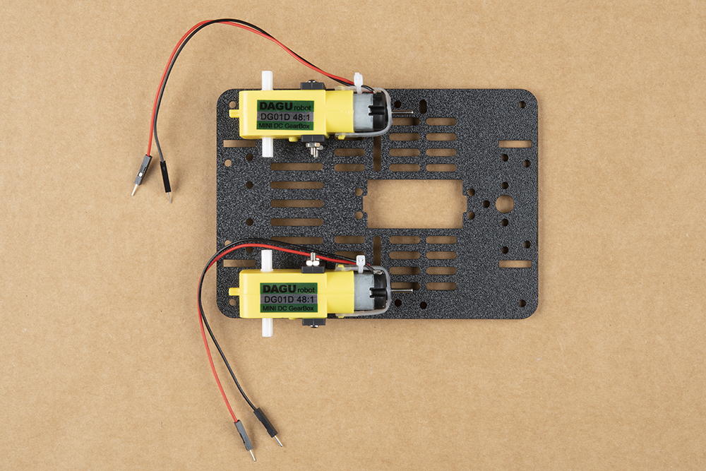
We prefer the shown orientation below that leaves the extra length of the machine screws & nuts on the inside edge of the JetBot.
Repeat this process on the other side of the chassis so both motors are symmetric on the base plate.
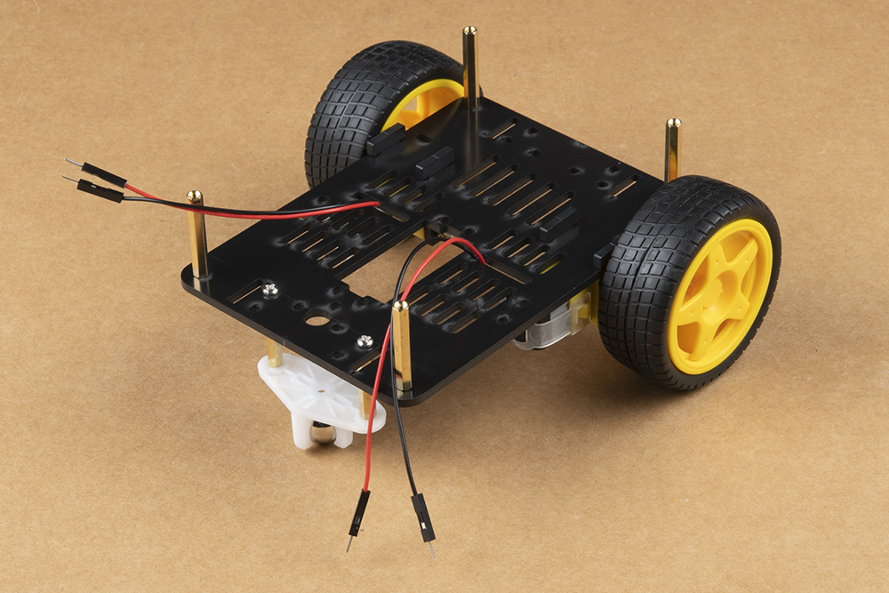
Once both motors are attached, flip the base plate over as pictured & attach the four longer brass standoffs at each corner of the base plate using the threaded screws included with the JetBot Chassis Kit. These four standoffs are packaged together. Thread one of the machine screws from the JetBot Chassis kit through the base plate & tighten into the brass standoff.
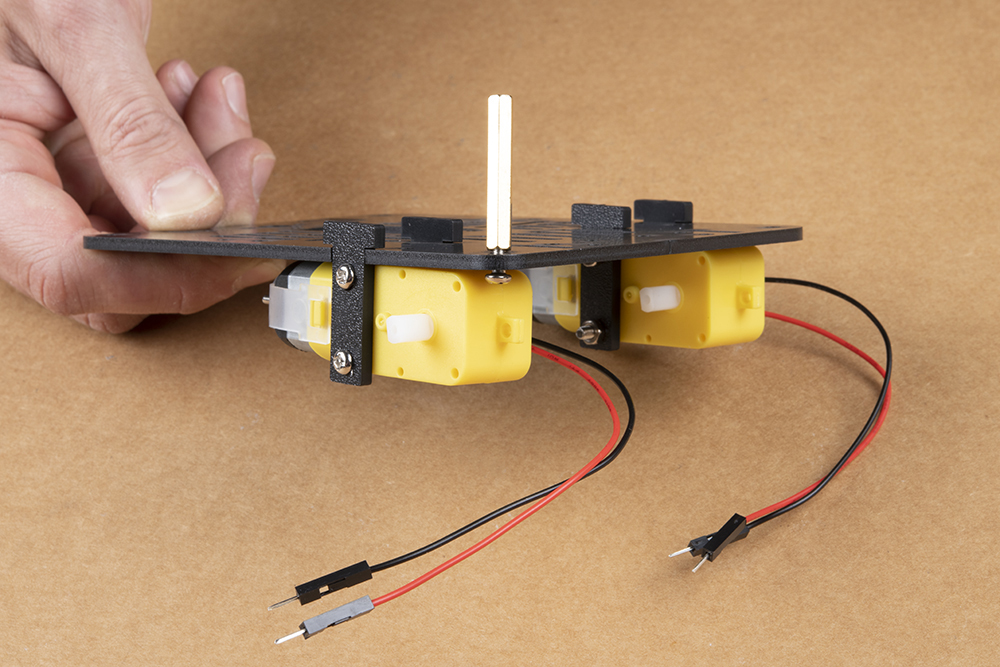
Repeat for each corner.
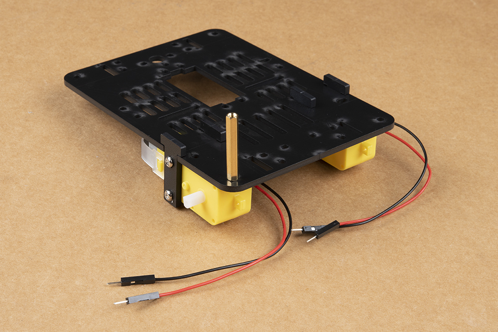
After all standoffs are installed, thread the motor terminal leads through the baseplate as shown. Refer to the photograph of the caster ball assembly to make sure you are using the correctly sized brass standoffs.

Next, gather the parts needed to assemble the caster ball assembly.
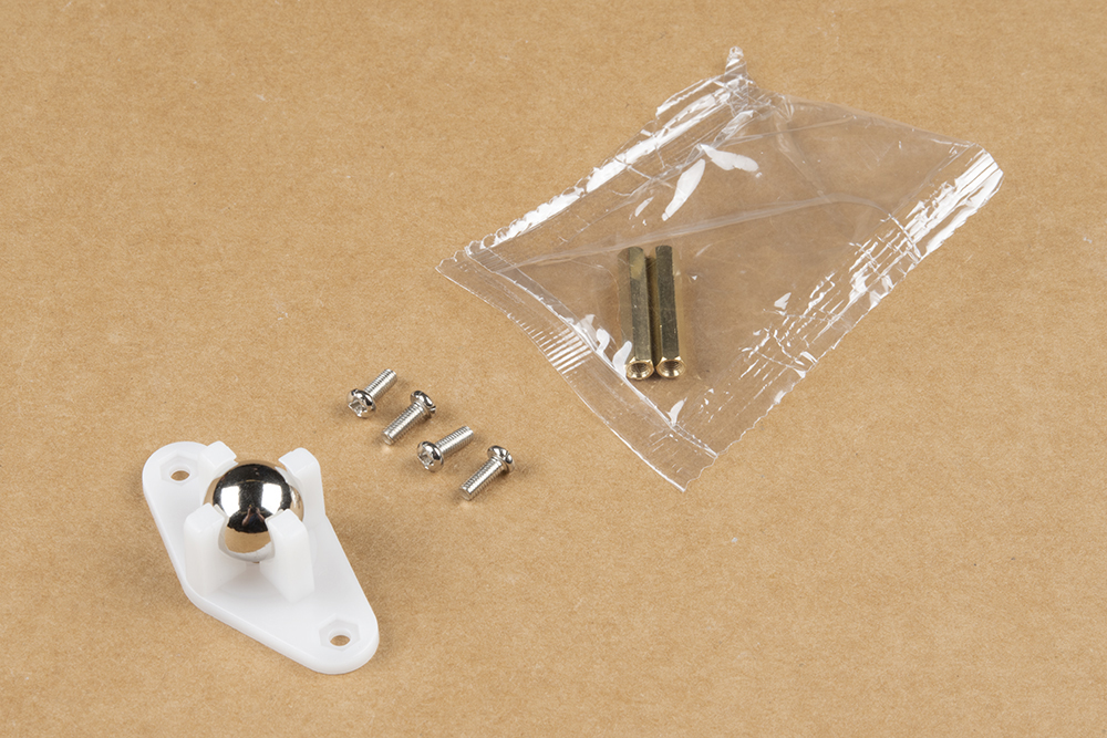
Notice that the brass standoffs used for the caster assembly are slightly shorter than those used for the chassis. The first time you build the SparkFun JetBot, each of these sets of standoffs are packaged together, but it is easy to confuse these once everything has been opened.

Flip the chassis over and install the shorter brass standoffs as shown in the photo below.

Use the two remaining screws to attach the caster ball casing to the brass standoffs.
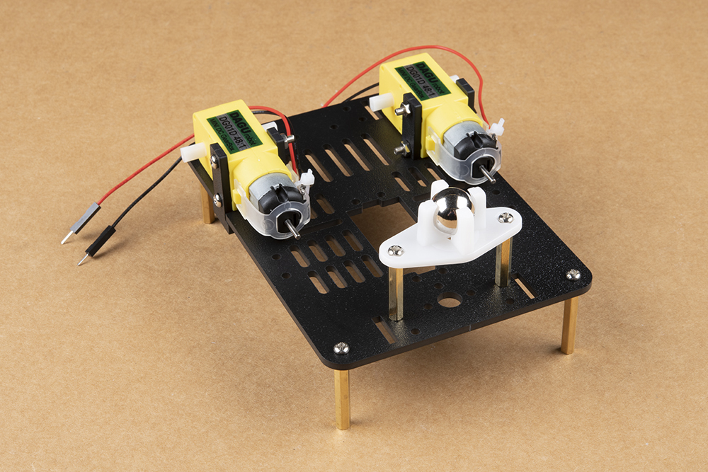
Press the wheels onto the hobby motor axles for a snug friction fit & flip it again Charley! Behold, a very stable three point stance foundation for you to build from.