AS726X NIR/VIS Spectral Sensor Hookup Guide
 Englandsaurus
 Introduction
The AS726X Spectral Sensors from AMS brings a field of study to consumers that was previously unavailable, spectroscopy! It's now easier than ever to measure and characterize how different materials absorb and reflect different wavelengths of light. Don't know what part of the spectrum you want to look at? You're in luck! Sparkfun carries two different flavors of spectrometer. The AS7262 detects wavelengths in the visible range while the AS7263 detects wavelengths just below the visible range, in the Near Infrared (NIR) range.

Required Materials
To follow along with this hookup guide, you will need one of the following Qwiic shields to match your preference of microcontroller:
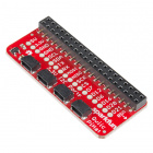

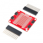
SparkFun Qwiic Shield for Photon
DEV-14477You will also need a Qwiic cable to connect the shield to your AS726X, choose a length that suits your needs.


Qwiic Cable - 50mm
PRT-14426
Qwiic Cable - 200mm
PRT-14428
Qwiic Cable - 500mm
PRT-14429Suggested Reading
If you aren't familiar with the Qwiic system, we recommend reading here for an overview.
| Qwiic Connect System |
We would also recommend taking a look at the following tutorials if you aren't familiar with them.
How to Solder: Through-Hole Soldering
Serial Communication
Light
I2C
Qwiic Shield for Arduino & Photon Hookup Guide
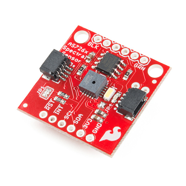
Hardware Overview
The AS7262 detects 450, 500, 550, 570, 600, and 650nm of light each with 40nm of full-width half-max detection. The AS7263 can detect 610, 680, 730, 760, 810, and 860nm of light each with 20nm of full-width half-max detection.
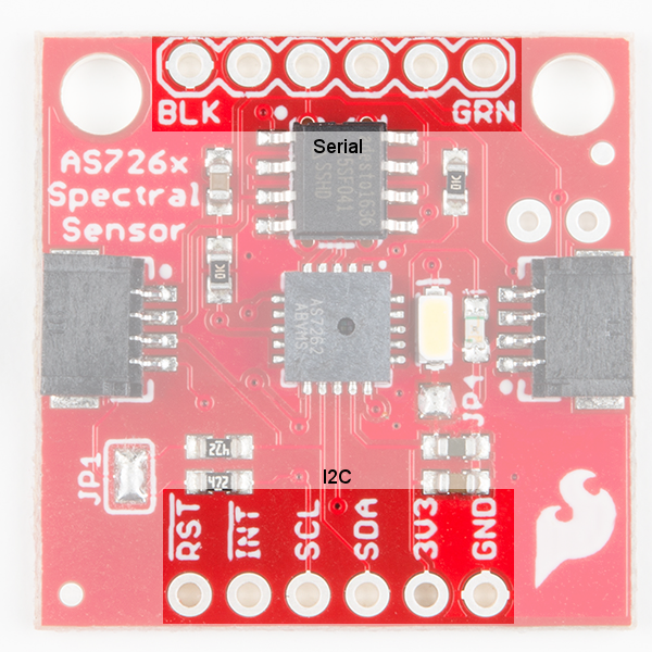
Communication
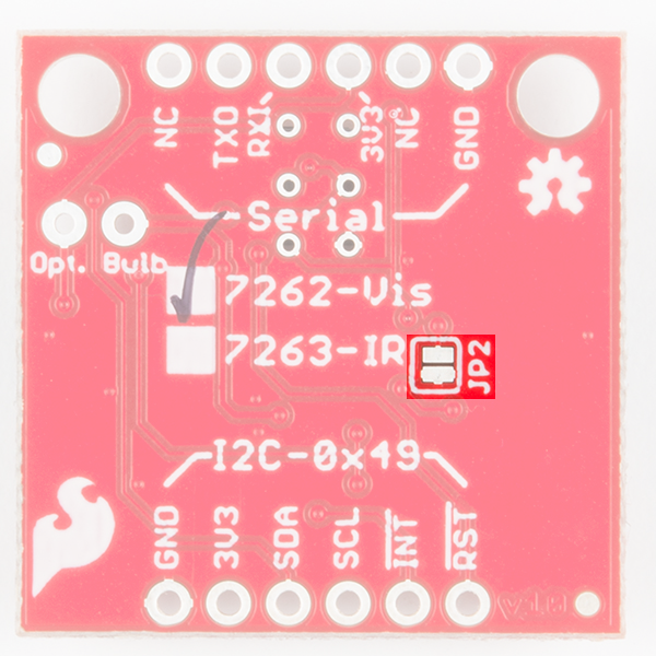
The AS726X is unique as it can communicate by both an I2C interface (through the onboard Qwiic connectors, or pins at the bottom of the board) and serial interface using AT commands (pins at the top of the board).
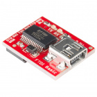
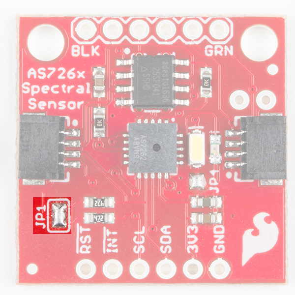
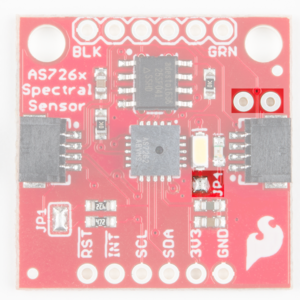
While I2C is the default setting (The default I2C address is 0x49 for both AS7262 and AS7263), serial communication via UART can be enabled by removing solder from the jumpers labeled JP1, adding solder to the jumper labeled JP2 (on the back of the board), and using Sparkfun's USB-to-Serial breakout to interface directly with the computer. JP1 also connects the I2C bus to pull-up resistors. If multiple sensors are connected to the bus with the pull-up resistors enabled, the parallel equivalent resistance will create too strong of a pull-up for the bus to operate correctly. As a general rule of thumb, disable all but one pair of pull-up resistors if multiple devices are connected to the bus. If you need to disconnect the pull up resistors they can be removed by removing the solder on jumper JP1 highlighted below.
 |
 |
LED
The board also has multiple ways for you to illuminate the object that you are trying to measure for a more accurate spectroscopy reading. There is an onboard, 5700K LED that has been picked out specifically for this task. However, if you aren't satisfied with the onboard LED, you can grab your own through hole incandescent. While you should find a bulb rated for 3.3V, a bulb rated for higher voltage, like 5V, will still work, but will not run as bright as it normally would with 5V. We've found that Mouser is a good place to look for these. If you are going to go that route and use your own bulb, be sure to disable the onboard LED by removing the solder from the JP4 jumper.
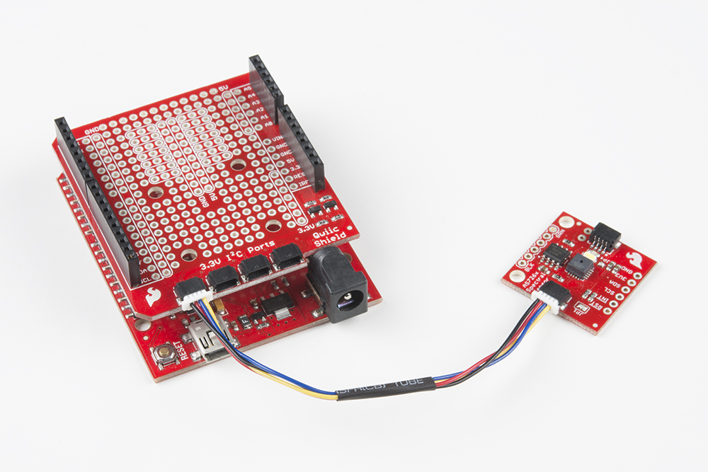
Hardware Assembly
The beauty of Sparkfun's new Qwiic environment means that connecting the sensor could not be easier. Just plug one end of the Qwiic cable into the AS726X, the other into one of the Qwiic Shields, and stack the board on a development board. You'll be ready to upload a sketch to start taking spectroscopy measurements. It seems too easy, but thats why we made it this way! Here's an example using the RedBoard Programmed with Arduino.
Library Overview
Note: This example assumes you are using the latest version of the Arduino IDE on your desktop. If this is your first time using Arduino, please review our tutorial on installing the Arduino IDE. If you have not previously installed an Arduino library, please check out our installation guide.
Before we get started, we'll need to download and install SparkFun's AS726X Arduino library. You can use the Arduino Library Manager by searching "SparkFun AS726X" to automatically install. Or you can download the library and install it using the button below.
Before we get started developing a sketch, let's look at the available functions of the library.
bool begin(TwoWire &wirePort, byte gain, byte measurementMode);--- Initializes the sensor with user given values for the wire port, gain, and measurementvoid takeMeasurements();--- Sensor writes spectral measurements to memory locations.void takeMeasurementsWithBulb();--- Illuminates onboard bulb, callstakeMeasurements();, then turns off the onboard bulb.byte getTemperature();--- Fetches the temperature in degrees Celsius.float getTemperatureF();--- Fetches the temperature in degrees Fahrenheit.void setMeasurementMode(byte mode);--- Changes the measurement mode to 0, 1, 2, or 3- 0: Continuous reading of VBGY (Visible) / STUV (IR)
- 1: Continuous reading of GYOR (Visible) / RTUX (IR)
- 2: Continuous reading of all channels
- 3: One-shot reading of all channels (power-on default)
boolean dataAvailable();--- Returnstrueorfalsebased on whether or not data is available to be read.void enableIndicator();--- Powers on the surface mounted blue indicator LED.void disableIndicator();--- Powers off the surface mounted blue indicator LED.void setIndicatorCurrent(byte current);--- Sets the current on the indicator LED. The default iscurrent = 3, or 8 mA.- 0: 1 mA
- 1: 2 mA
- 2: 4 mA
- 3: 8 mA
void enableBulb();--- Powers on the surface mounted blue indicator LED.void disableBulb();--- Powers off the surface mounted blue indicator LED.void setBulbCurrent(byte current);--- Sets the current limit on the indicator LED and optional bulb (They are connected in parallel) The default iscurrent = 0or 12.5 mA.- 0: 12.5 mA
- 1: 25 mA
- 2: 50 mA
- 3: 100 mA
void softReset();--- Gives the sensor a 1 second reset.void setGain(byte gain);--- Pass in a 0, 1, 2 or 3 to change the gain.- 0: 1x
- 1: 3.7x
- 2: 16x
- 3: 64x (power-on default)
void setIntegrationTime(byte integrationValue);--- This sets the time over which samples are taken.- Takes a value between 0 and 255.
- Integration time will be 2.8 ms *
integrationValue.
void enableInterrupt();--- Pulls the interrupt pin low. (Note: not yet implemented)void disableInterrupt();--- Pulls the interrupt pin high.- If you'd like access to just one channel, getting uncalibrated and calibrated spectral readings for the AS7262 (Visible) sensor can be accomplished with the following commands:
int getViolet();int getBlue();int getGreen();int getYellow();int getOrange();int getRed();float getCalibratedViolet();float getCalibratedBlue();float getCalibratedGreen();float getCalibratedYellow();float getCalibratedOrange();float getCalibratedRed();
- A similar set of functions is available for accessing individual channels on the AS7263 (Near Infrared) sensor.
int getR();int getS();int getT();int getU();int getV();int getW();float getCalibratedR();float getCalibratedS();float getCalibratedT();float getCalibratedU();float getCalibratedV();float getCalibratedW();
Example Code
Example 1 --- Basic Readings
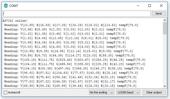
The below sketch will get you up and running taking calibrated spectral readings on all 6 channels. Once this sketch is uploaded, open the serial monitor with a baud rate of 115200 to display the spectral data from the sensor.
language:c
#include "AS726X.h"

AS726X sensor;

void setup() {
  Wire.begin();
  Serial.begin(115200);

  sensor.begin();
}

void loop() {
  sensor.takeMeasurements();
  //Prints all measurements
  if (sensor.getVersion() == SENSORTYPE_AS7262)
  {
    //Visible readings
    Serial.print(" Reading: V[");
    Serial.print(sensor.getCalibratedViolet(), 2);
    Serial.print("] B[");
    Serial.print(sensor.getCalibratedBlue(), 2);
    Serial.print("] G[");
    Serial.print(sensor.getCalibratedGreen(), 2);
    Serial.print("] Y[");
    Serial.print(sensor.getCalibratedYellow(), 2);
    Serial.print("] O[");
    Serial.print(sensor.getCalibratedOrange(), 2);
    Serial.print("] R[");
    Serial.print(sensor.getCalibratedRed(), 2);
  }
  else if (sensor.getVersion() == SENSORTYPE_AS7263)
  {
    //Near IR readings
    Serial.print(" Reading: R[");
    Serial.print(sensor.getCalibratedR(), 2);
    Serial.print("] S[");
    Serial.print(sensor.getCalibratedS(), 2);
    Serial.print("] T[");
    Serial.print(sensor.getCalibratedT(), 2);
    Serial.print("] U[");
    Serial.print(sensor.getCalibratedU(), 2);
    Serial.print("] V[");
    Serial.print(sensor.getCalibratedV(), 2);
    Serial.print("] W[");
    Serial.print(sensor.getCalibratedW(), 2);
   }

  Serial.print("] tempF[");
  Serial.print(sensor.getTemperatureF(), 1);
  Serial.print("]");

  Serial.println();
}
If we want, we can change the gain, measurement mode, and Wire that I2C uses by calling the begin() function with a few arguments. First, let's look at what values we can assign to which characteristic.
Example 2 --- Sensor Settings
The below example code will initialize our sensor with a gain of 16x, measurement mode of 0, and our regular I2C port (you can run the sensor on a different I2C port if you have the right hardware, a Teensy perhaps?).
language:c
#include "AS726X.h"
AS726X sensor;//Creates the sensor object
byte GAIN = 0;
byte MEASUREMENT_MODE = 0;

void setup() {
  Wire.begin();
  Serial.begin(115200);

  sensor.begin(Wire, GAIN, MEASUREMENT_MODE);//Initializes the sensor with non default values
}

void loop() {
  sensor.takeMeasurements();

  if (sensor.getVersion() == SENSORTYPE_AS7262)
   {
    //Visible readings
    Serial.print(" Reading: V[");
    Serial.print(sensor.getCalibratedViolet(), 2);
    Serial.print("] B[");
    Serial.print(sensor.getCalibratedBlue(), 2);
    Serial.print("] G[");
    Serial.print(sensor.getCalibratedGreen(), 2);
    Serial.print("] Y[");
    Serial.print(sensor.getCalibratedYellow(), 2);
    Serial.print("] O[");
    Serial.print(sensor.getCalibratedOrange(), 2);
    Serial.print("] R[");
    Serial.print(sensor.getCalibratedRed(), 2);
  }
  else if (sensor.getVersion() == SENSORTYPE_AS7263)
  {
    //Near IR readings
    Serial.print(" Reading: R[");
    Serial.print(sensor.getCalibratedR(), 2);
    Serial.print("] S[");
    Serial.print(sensor.getCalibratedS(), 2);
    Serial.print("] T[");
    Serial.print(sensor.getCalibratedT(), 2);
    Serial.print("] U[");
    Serial.print(sensor.getCalibratedU(), 2);
    Serial.print("] V[");
    Serial.print(sensor.getCalibratedV(), 2);
    Serial.print("] W[");
    Serial.print(sensor.getCalibratedW(), 2);
  }

  Serial.print("] tempF[");
  Serial.print(sensor.getTemperatureF(), 1);
  Serial.print("]");

  Serial.println();
}
Expected Output
Here is a picture of what to expect when bringing your AS726X online for either of the above sketches. (The program will print "AS7263 online!" instead if you have that sensor)
Resources and Going Further
Now that you've successfully got your AS726X up and running, it's time to incorporate it into your own project!
For more information, check out the resources below:
- AS726X Schematic (PDF) - Schematic for both the AS7262 and AS7263.
- AS726X Eagle Files (ZIP) - Board design files for both the AS7262 and AS7263.
- AS7262 Datasheet (PDF) - Datasheet for AS7262 Visible Sensor.
- AS7263 Datasheet (PDF) - Datasheet for AS7263 NIR Sensor.
- Product Showcase: Qwiic AS726X
- Qwiic System Landing Page
- Arduino Library
- SparkFun AS726X GitHub Repository -- Hardware repo
Using both the AS7263 NIR and AS7262 VIS sensors in the same I2C bus? Try using the Qwiic MUX board since they have the same I2C address!
Qwiic MUX Hookup Guide
Need some inspiration for your next project? Check out some of these related tutorials: