APDS-9301 Sensor Hookup Guide
 SFUptownMaker
Example
Hardware Hookup
We use a hookup as pictured below for our example project. However, this basic Arduino code should work for any number of different Arduino compatible boards. In this case, we show it on an Arduino Pro 3.3V, to allow the setup to work without any level translation between the Arduino and the APDS-9301.

Note that this setup requires some soldering. New to soldering? Check out our through hole soldering guide!
Notes on Operation
The APDS-9301 has two internal light sensing elements: CH0, which responds to infrared and visible light, and CH1, which responds to only visible light. By combining these two channels, the sensor is able to compensate for local infrared light and provide a more accurate estimate of the current lux value.
The calculation of lux reading from CHO and CH1 sensor output readings is not straightforward. The function is piecewise, with different coefficients depending on the ratio CH1/CH0. This function is automatically implemented in the readLuxLevel() library function, but can be found in the datasheet if you're curious.
The APDS-9301 sensor works by multiplying the light input signal by a gain (either 1x or 16x) and then using an integrating ADC to measure the light input over some integration time. As such, the integration time imposes an inherent limit on the maximum reading of the ADC. For the 13.7ms integration time, this limit is 5047. For the 101ms integration time, this limit is 37177. For the full 402ms integration time, the maximum is actually defined by the size of the output variable, an 16-bit unsigned integer, at 65535. This fact should be taken into account when selecting a value for the interrupt high and low threshold values. For instance, if the integration time is 13.7ms and a high threshold of 6000 is set, that threshold will never be reached.
Example Code
Note: This example assumes you are using the latest version of the Arduino IDE on your desktop. If this is your first time using Arduino, please review our tutorial on installing the Arduino IDE. If you have not previously installed an Arduino library, please check out our installation guide.
Make sure to install the APDS-9301 Arduino library before using the example code. You can obtain the library through the Arduino Library Manager by serarching for "SparkFun APDS-9301 Lux Sensor" in order to install the latest version. The library can also be found in the SparkFun APDS-9301 Library GitHub repository to manually install:
Below is a simple example code for Arduino that uses the APDS-9301 library. First, the example code sets the gain and integration time. Then enables and sets thresholds for the interrupt. Finally, the code reads the current lux level and prints it to the serial port. It also prints a message when the light level exceeds a certain threshold. It should get you up and running in no time!
language:c
#include "Wire.h"
#include <Sparkfun_APDS9301_Library.h>

APDS9301 apds;

#define INT_PIN 2 // We'll connect the INT pin from our sensor to the
                  // INT0 interrupt pin on the Arduino.
bool lightIntHappened = false; // flag set in the interrupt to let the
                  //  mainline code know that an interrupt occurred.

void setup()
{
  SerialUSB.begin(115200);
  Wire.begin();

  // APDS9301 sensor setup.
  apds.begin(0x39);  // We're assuming you haven't changed the I2C
                     //  address from the default by soldering the
                     //  jumper on the back of the board.
  apds.setGain(APDS9301::LOW_GAIN); // Set the gain to low. Strictly
                     //  speaking, this isn't necessary, as the gain
                     //  defaults to low.
  apds.setIntegrationTime(APDS9301::INT_TIME_13_7_MS); // Set the
                     //  integration time to the shortest interval.
                     //  Again, not strictly necessary, as this is
                     //  the default.
  apds.setLowThreshold(0); // Sets the low threshold to 0, effectively
                     //  disabling the low side interrupt.
  apds.setHighThreshold(50); // Sets the high threshold to 500. This
                     //  is an arbitrary number I pulled out of thin
                     //  air for purposes of the example. When the CH0
                     //  reading exceeds this level, an interrupt will
                     //  be issued on the INT pin.
  apds.setCyclesForInterrupt(1); // A single reading in the threshold
                     //  range will cause an interrupt to trigger.
  apds.enableInterrupt(APDS9301::INT_ON); // Enable the interrupt.
  apds.clearIntFlag();

  // Interrupt setup
  pinMode(INT_PIN, INPUT_PULLUP); // This pin must be a pullup or have
                     //  a pullup resistor on it as the interrupt is a
                     //  negative going open-collector type output.
  attachInterrupt(digitalPinToInterrupt(2), lightInt, FALLING);
}

void loop()
{
  static unsigned long outLoopTimer = 0;
  apds.clearIntFlag();

  // This is a once-per-second timer that calculates and prints off
  //  the current lux reading.
  if (millis() - outLoopTimer >= 1000)
  {
    outLoopTimer = millis();

    SerialUSB.print("Luminous flux: ");
    SerialUSB.println(apds.readLuxLevel(),6);

    if (lightIntHappened)
    {
      SerialUSB.println("Interrupt");
      lightIntHappened = false;
    }
  }
}

void lightInt()
{
  lightIntHappened = true;
}
After uploading code, try opening the Arduino serial monitor at 115200 baud and observe the sensor's output.
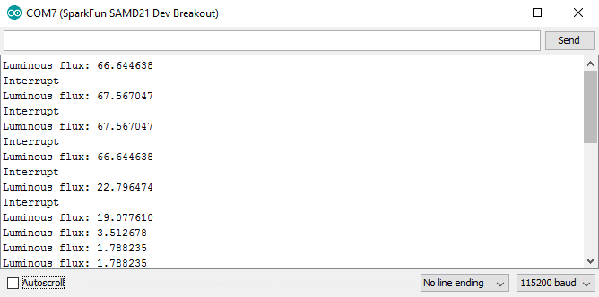
As you can see, once per second, the sketch will print the luminous flux and whether or not the level selected for an interrupt has been exceeded.