Analog MEMS Microphone (VM2020) Hookup Guide
 QCPete,
  bboyho
Hardware Hookup
Now that we're familiar with the microphone breakout, let's connect it to a microcontroller and monitor some sound!
Microphone Breakout Connections
For a permanent connection, we recommend soldering four wires (or headers) to the PTHs on the breakout. We opted for soldering header pins and using jumper wires. Of course, you could also solder wires to the breakout board as well. For a temporary connection during prototyping, you can use IC hooks like these.
How to Solder: Through-Hole Soldering
Working with Wire
We recommend soldering right angle headers. Right angle headers will provide a low height profile. This is more versatile as users can angle the microphone or add M/F jumper wires between the board and breadboard. The microphone will also sit up and away from the board.


Straight header pins being soldered to MEMS microphone.
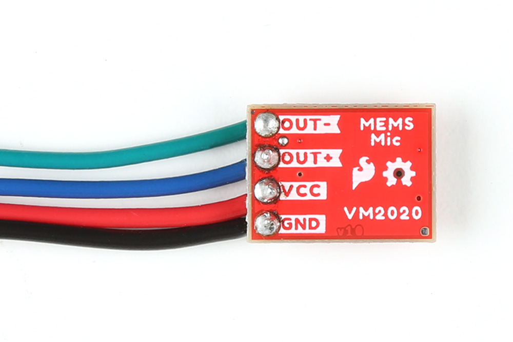
However, depending on your application, you can also solder wires to the board. We recommend using the following colors of wire to easily distinguish the signals but you can always select a different color if you prefer (or do not have the colors used available).
Right angle header pins being soldered to MEMS microphone.
- Green (or some other color not Red or Black) for Output−
- Blue (or some other color not Red or Black) for Output+
- Red for VCC
- Black for GND
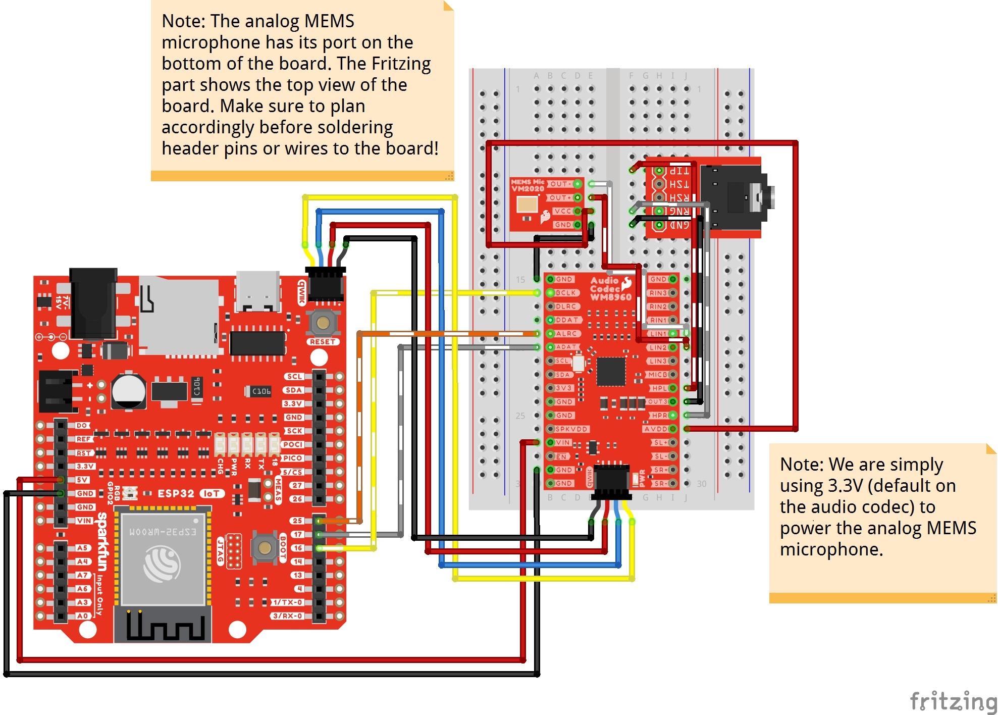
Connecting to a Microcontroller and Audio Codec WM8960
Next up we'll connect the breakout to an audio codec to amplify and read the signal. Then we will connect the boards to a microcontroller to monitor the audio signal output. For this tutorial, we used the MEMS microphone with the audio codec WM8960 and SparkFun IoT RedBoard - ESP32. The ESP32 module has I2S support and is recommended in this setup with the WM8960. Make the following connections between the breakout and IoT RedBoard - ESP32 (or whichever ESP32 variant that you choose).
| IoT RedBoard - ESP32 (or Arduino) | MEMS Microphone | WM8960 | TRS Connector |
|---|---|---|---|
| 5V | VIN | ||
| Qwiic Cable's SCL pin (or SCL) |
Qwiic Cable's SCL pin (or SCL) |
||
| Qwiic Cable's SDA pin (or SDA) |
Qwiic Cable's SDA pin (or SDA) |
||
| Qwiic Cable's 3.3V pin (or 3.3V) |
Qwiic Cable's 3.3V pin (or 3.3V) |
||
| Qwiic Cable's GND pin (or GND) |
Qwiic Cable's GND pin (or GND) |
||
| Output − | LIN1 | ||
| Output + | LIN2 | ||
| GND | GND | ||
| VCC | AVDD (i.e. 3.3V) |
||
| 25 | ALRC | ||
| 17 | ADAT | ||
| 16 | BCLK | ||
| HPL | TIP | ||
| OUT3 | GND (i.e. Sleeve) | ||
| HPR | RNG (i.e. Ring) |
The completed circuit should look something like the photo below: