ACS712 Low Current Sensor Hookup Guide
This Tutorial is Retired!
Note: This tutorial is for the ACS712 Current Sensor Breakout Boards. If you are using either of the newer ACS723 Breakout Boards, please refer to the new Current Sensor Breakout (ACS723) Hookup Guide.
View the updated tutorial: Current Sensor Breakout (ACS723) Hookup Guide
The Hall Effect and Current Sensors
This section provides a quick recap of electromagnetic concepts that make this current sensor possible. How does this little chip take current from one circuit and produce a proportional output voltage without physically connecting the two circuits?
Faraday's Law of Induction
In the ACS712, sensing current starts with a phenomena known as Faraday's Law (of Induction). This phenomena, first discovered by Michael Faraday in 1831, is a foundation of modern radio and electromagnetics. This law describes how an electrical current flowing in a conductor creates a surrounding magnetic field, and how a changing magnetic field can create, or induce, a current in a conductor. This is how antennas pick up radio waves!

The current pins of the ACS712 are internally connected to a big trace of copper, allowing a lot of electricity to flow through this part of the chip. When current flows through the copper strip, a magnetic field is created around the trace with a strength proportional to the current.
The Hall Effect
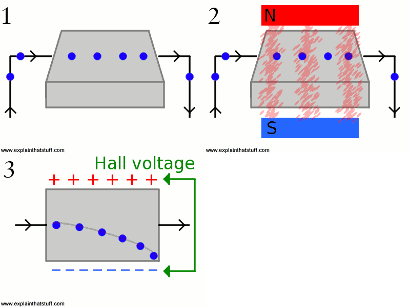
The next step in sensing current is based on the Hall effect - a very useful phenomena discovered by Edwin Hall in 1879. In basic terms, the Hall effect produces a voltage difference across a conductor in the presence of a magnetic field. This provides a neat way of sensing nearby magnetic fields and has many applications. Hall effect sensors are used in some car engines to detect where in a rotation cycle the camshaft or crankshaft are, for example.

The ACS712 has an internal Hall effect sensor placed next to the aforementioned copper strip. When current flows through this copper strip, a magnetic field is created. This magnetic field is then sensed by the Hall effect sensor and produces a voltage output that is proportional to the input current!
This method of sensing allows the sensing circuit to be electrically isolated from the sensed circuit. Practically, this means that since the circuits aren't physically connected, you can use a low-power Arduino to measure the current going through a high power device, even one that uses AC power!
