ACS712 Low Current Sensor Hookup Guide
This Tutorial is Retired!
Note: This tutorial is for the ACS712 Current Sensor Breakout Boards. If you are using either of the newer ACS723 Breakout Boards, please refer to the new Current Sensor Breakout (ACS723) Hookup Guide.
View the updated tutorial: Current Sensor Breakout (ACS723) Hookup Guide
 AGlass0fMilk
Hardware Overview
This section will explore the various segments of the breakout.
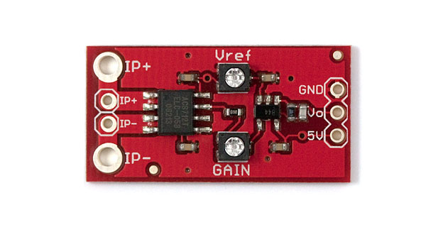
ACS712 Breakout Details:
- Analog output with bandwidth adjustable to 80kHz.
- The bandwidth on the ACS712 Low Current Sensor Breakout with filter has been set to 34kHz to reduce noise when using at high gains. The full 80KHz bandwidth that the sensor is capable of can be recovered by removing C1. See schematic for more details.
- Measures DC and AC currents from around 10mA up to 5A
- Adjustable sensitivity with on-board amplifier, gain from 4.27 to 47 V/V
- The version without the op-amp has a base sensitivity of 185mV/A
- Full electrical isolation of measured and sensed circuits
Below is a list of all the pins broken out on the ACS712 and their function.
| Symbol | Description |
|---|---|
| IP+ | High side of current sensor |
| IP- | Low side of current sensor |
| GND | Must be connected to ground |
| Vo | Voltage output proportional to current flowing through IP+ and IP- |
| 5V | 5V power supply |
To measure a current using this device, the current must flow through the IP+ terminal and out the IP- terminal (it will work in the other direction, but the measurement will be negative). IE: These terminals must be in series with the circuit the measured current is flowing through. Note that both IP+ and both IP- terminals are connected to each other, you can use either (or both) of them.
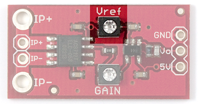
This amplified version of the breakout board has two potentiometers on it: Vref and Gain
The Vref potentiometer sets the baseline voltage output. In other words, it adjusts the voltage seen at Vo when there is no current flowing through the sensor (0 mA). This allows the sensor to output negative current readings as well as positive.
The gain potentiometer sets the sensitivity of the device. For example, if the gain is set high, then a smaller current will cause the voltage output to increase more, giving you higher sensitivity and allowing you to sense smaller currents.
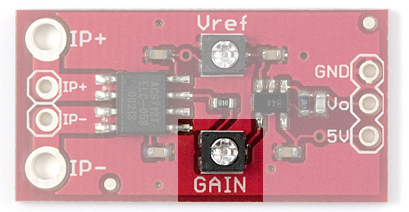
However there are a couple caveats:
- With higher gain you will see more noise (spikes) on the output, so smaller currents will be harder to measure accurately.
- If you are trying to measure larger currents with a high gain setting, your output will saturate or clip and reach the maximum 5V or 0V.
With that in mind, to get meaningful data from the current sensor, you must configure the Vref and gain potentiometers properly.