SparkFun Clock Generator 5P49V60 (Qwiic) Hookup Guide
 Elias The Sparkiest
Introduction
The SparkFun Clock Generator 5P49V60 breakout board offers a wide range of customizable frequencies in a wide range of different signal types using a single reference clock. Four (single output) clock outputs can generate frequencies from 1MHz-200MHz and eight (differential output) clock outputs can generate frequencies from 1MHz-350MHz. The frequency's many properties can be manipulated in code via I2C using the SparkFun Arduino Library. The SparkFun Clock Generator also has four banks of programmable memory for the time when it's ready to sit on its' own within the project without a microcontroller. This hookup guide will go over all of the many available functions of the SparkFun Clock Generator and gives the hardware rundown on what exactly is on this board.

Required Materials
To follow along with this tutorial, you will need the following materials. You may not need everything though depending on what you have. For example, I chose the RedBoard Qwiic as a simple demo, but you could use any microcontroller. Add it to your cart, read through the guide, and adjust the cart as necessary.
Required Tools
An oscilloscope is highly recommended to verify that the programmed clock signal is correct as its the only way to verify the output accurately. SparkFun only has a few oscilloscopes in its' catalog, but if it's time to add this essential Electrical Engineering tool to your work bench, then check out SparkFun's offerings below. You will also need to have a soldering iron to connect to the clock output pins!
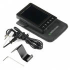

SparkFun Beginner Tool Kit
TOL-14681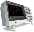
Digital Storage Oscilloscope - 100MHz (TBS2104)
TOL-14925Suggested Reading
If you aren't familiar with the Qwiic system, we recommend reading here for an overview.
| Qwiic Connect System |
We would also recommend taking a look at the following tutorials if you aren't familiar with them. In particular the tutorial on how to use an oscilloscopes might be very helpful depending on your experience.
I2C
How to Use an Oscilloscope
How to Work with Jumper Pads and PCB Traces
Hardware Overview
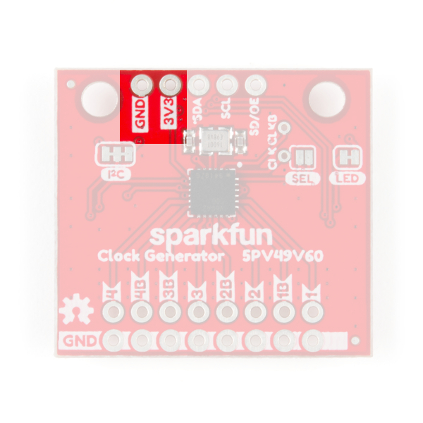
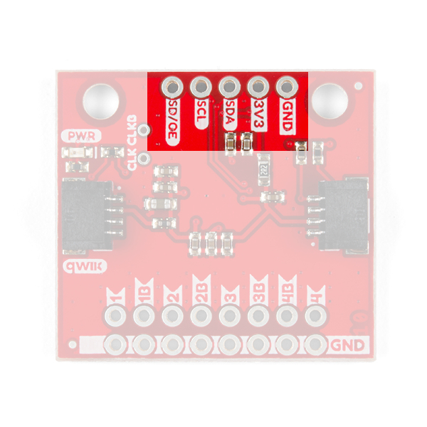
Power
Power can be supplied through the header along the top side of the board labeled 3.3V and GND. Alternatively, power can be supplied through the Qwiic connectors on either side of the board.
 |
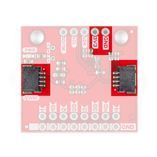 |
| Top View of Input Power | Bottom View of Qwiic Connectors |
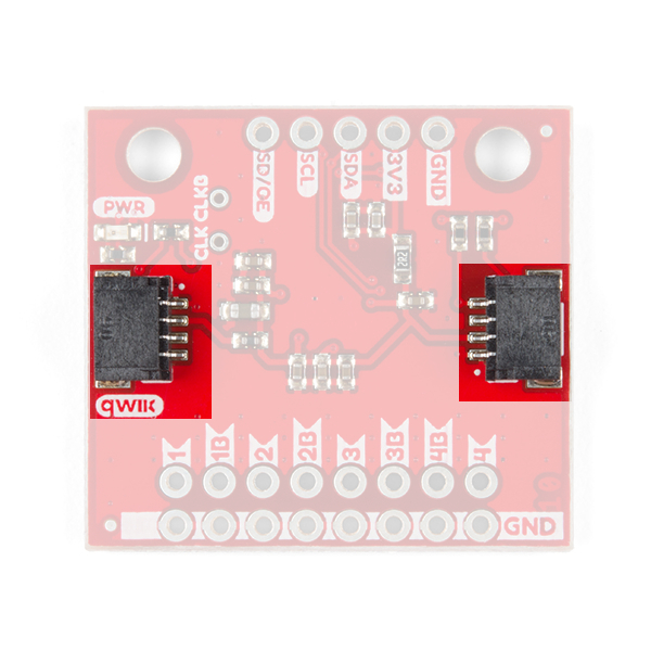
Qwiic Connectors
There are two Qwiic connectors on either end of the SparkFun Clock Generator to provide power and I2C connectivity simultaneously. The I2C address of the board is 0x6A by default [ 1 ]. The address can be changed to 0x68 using the library. The Qwiic ecosystem is made for fast prototyping by removing the need for soldering I2C data lines. However, in this case soldering is required to connect to the clock outputs.
0.
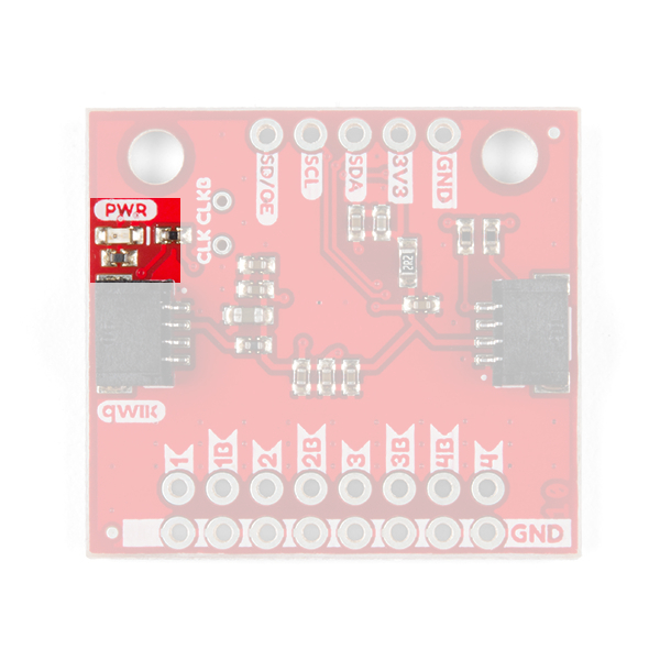
LED
There's a single red power LED, labeled PWR, on the bottom side of the board which indicates power is being supplied to the board.
Jumpers
There are three jumpers on the SparkFun Clock Generator.
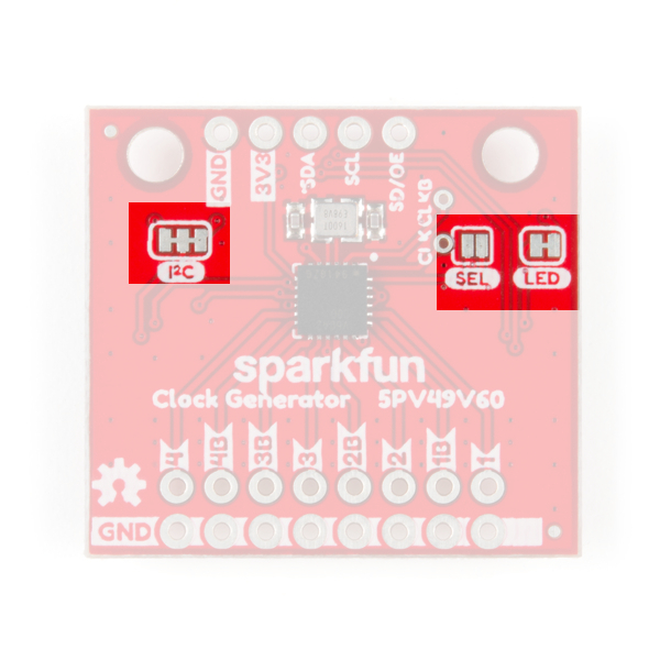
LED
Let's start with the jumpers on the right side of the board. The jumpers labeled LED can be cut to disconnect the red power LED so that it doesn't come on when power is supplied to the board. Not sure how to cut a jumper? Read here!
SEL
The second jumper labeled SEL enables the ability to load settings from the SparkFun's Clock Generators' One Time Programming memory banks. This disables the I2C data communication, turning those lines into selection pins. More information can be found down further under One Time Programming.
I2C
Finally, the jumpers labeled as I2C can be cut to disable the pull-up resistors on the I2C bus. In general, you shouldn’t need to mess with this jumper. But if you have many devices on your I2C bus, you may want to remove these resistors by cutting the two small traces between the solder pads.
Headers
There are two rows of headers on the SparkFun Clock Generator: one set contains all of the clock outputs while the other has I2C and a Shutdown/Output Enable Pin. There are also two pins just off-center of the board where a clock signal can be supplied to the board in place of the SparkFun Clock Generator's crystal.
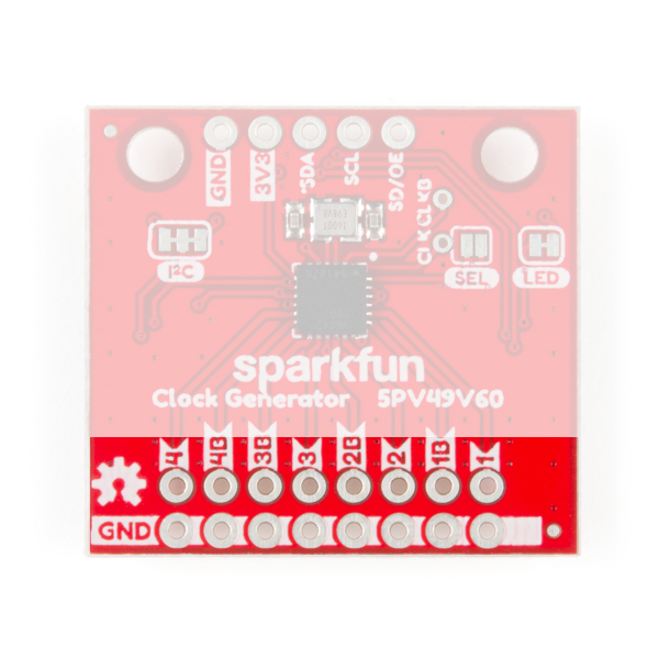
Clock Output
The clock output header is located at the bottom of the board. There are four possible clock signals with four complementary signals for differential clock transmission. Each set of outputs, 1-4B, has it's own frequency output divider that allows for customizable outputs. Below are example sketches for SparkFun's Arduino Library that demonstrates how to easily set these frequencies.
 |
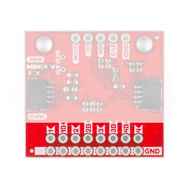 |
| Top View of Clock Output | Bottom View of Clock Output |
I2C
On the opposite edge from the clock output header is header for I2C and a pin labeled SD/OE. The software configurable pin labeled SD/OE stands for "Shutdown/Output Enable" and serves a dual purpose of shutting down the IC or turning on and off the clock outputs. By default this pin acts as an output enable, disabling the clocks when held low. In the SparkFun Arduino Library, you can use the function: sdInputPinControl(byte control) to enable shutdown instead.
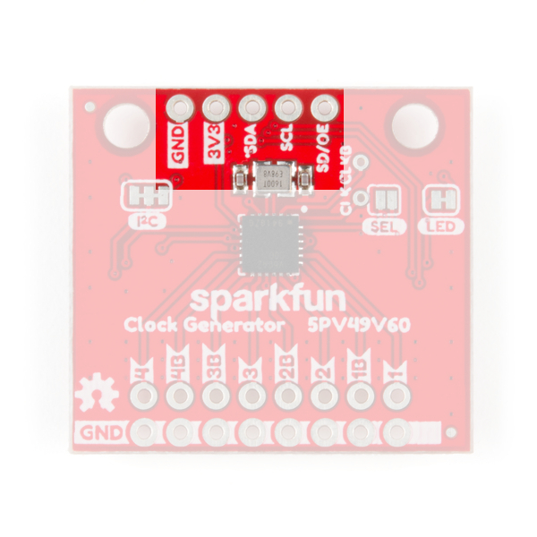 |
 |
| Top View of I2C and Shutdown/Output Enable Pins | Bottom View of I2C and Shutdown/Output Enable Pins |
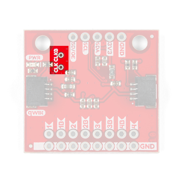
Alternate Clock Input Header
Just to the right of the SparkFun Clock Generator's Crystal - the little silver box just above the main IC, are two small holes labeled CLKIN and CLKINB. Using this small header it's possible to feed the SparkFun Clock Generator an external reference clock in place of the on-board crystal. There are two pins, but CLKIN can be used exclusively for single ended clock input. There is an Arduino example below that demonstrates how to enable this feature in code but more information on the hardware connectivity can be found on page 20 of the datasheet.
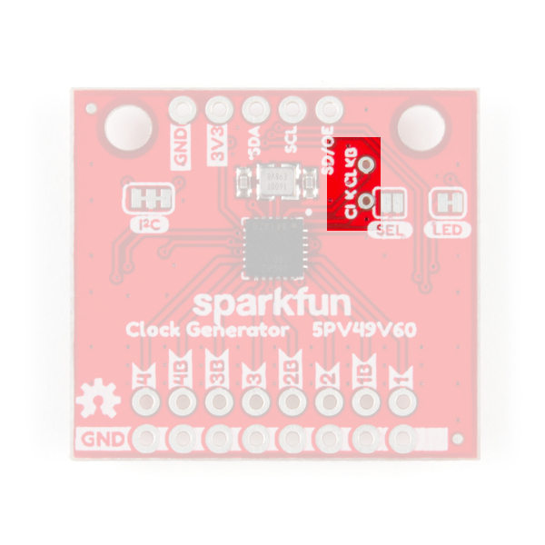 |
 |
| Top View w/ Clock Input Header | Bottom View w/ Clock Input Header |
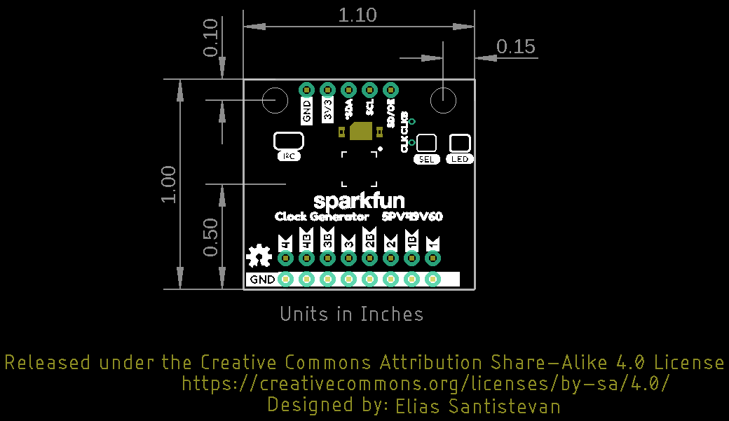
Board Dimensions
The overall board size is 1.10"x1.00". There are two mounting holes available on the board.
Clock Output Frequency
The SparkFun Clock Generator generates frequencies by using the small onboard crystal just above the IC in the center, as a reference clock. The diagram shown below from the datasheet displays how this works internally.
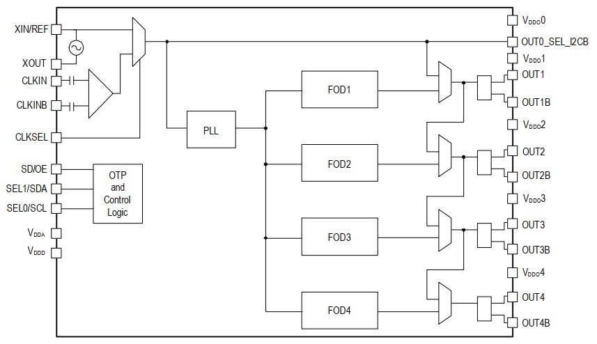
The reference clock (upper left two topmost pins) is manipulated internally in a phase lock loop (PLL center) to generate a frequency for the output dividers (FOD 1-4). These output dividers then set the frequencies for their respective clock outputs. These outputs are capable of frequencies between 1MHz-200MHz for single ended output or 1MHz-350MHz for differential signal output (see table in next section for specifics). It is possible to get even lower frequencies by feeding the output of one clock to the output divider of another clock in software. This is demonstrated in Arduino Example 6: Multiplex Clock Output below.
Each output divider for each clock is synchronized to maintain a low skew rate (phase of each clock) which can be programatically manipulated. In addition, the slew rate (rise and fall times) for each clock can also be set with one of four settings (see table below). Finally, a spread spectrum can be applied to the clock to reduce it's EMI or to increase it's robustness.
For each clock signal a corresponding signal type must be selected and proper hardware terminations must be applied accordingly. This is explained with some detail in the next section.
Slew rate
Below is the possible slew rate settings for the output frequencies at 3.3V.
| Slew Rates - 3.3V | |||
|---|---|---|---|
| Library Constant | Minimum | Typical | Units |
SLOWEST
|
1.0 | 2.2 | V/ns |
SLOW
|
1.2 | 2.3 | V/ns |
FAST
|
1.3 | 2.4 | V/ns |
FASTEST
|
1.7 | 2.7 | V/ns |
Signal Types and Termination
The SparkFun Clock Generator outputs different types of clock signals that each require their own specific hardware terminations. The following transmission outputs are available:
| Single Ended Output | Differential Signal Output | |
|---|---|---|
| Frequency Range | 1MHz - 200MHz | 1MHz - 350MHz |
| CMOS | LVPECL | |
| CMOS2 | LVDS | |
| CMOSD | HCSL33 |
In addition, transmission of these signals require ~50Ω trace impedance to avoid attenuation and distortion of the clock signal. Towards this goal, the board has been designed with 60Ω trace impedance with the shortest length possible between the header and the IC. The difference between the ideal trace and the Sparkfun Clock Generator's impedance can be remedied with series resistors or proper terminations and may not even be an issue depending on the selected frequency.
The selected signal type will require a different hardware termination. Below are the hardware terminations found in the 5P49V60 Clock Generator's datasheet.
| Signal Type | Hardware Termination |
|---|---|
| LVCMOS | 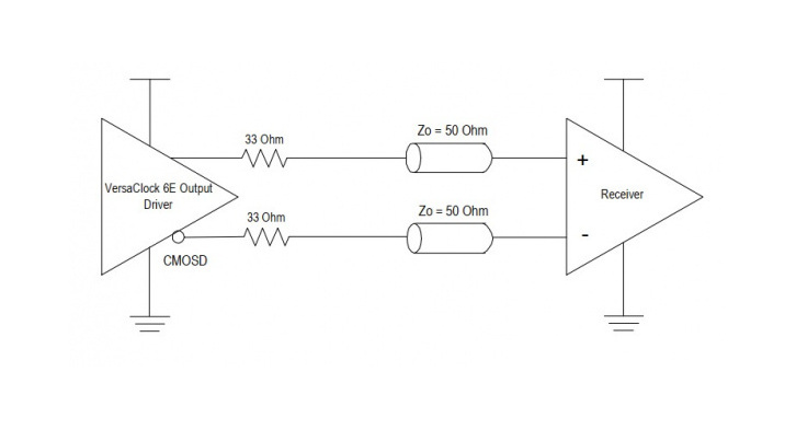
|
| LVPECL | 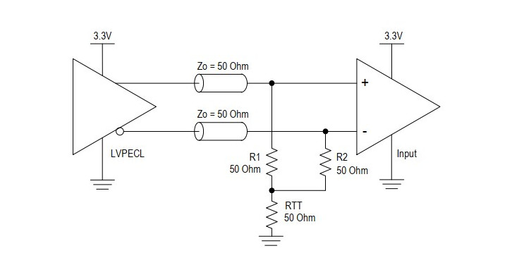
|

|
|
| LVDS | 
|
| HCSL33 Driver | 
|
| HCSL33 Source | 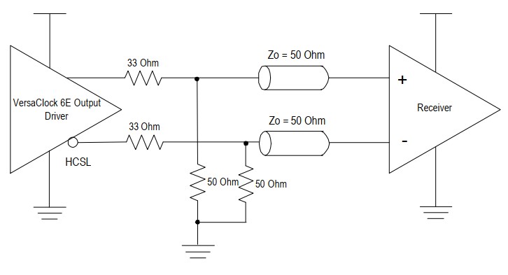
|
One Time Programming (OTP)
The SparkFun Clock Generator can save all of the programmed settings to any of its four programmable banks of RAM. However, keep in mind that this RAM can only be programmed once (One Time Programmable)! After programming any of the banks of memory, it's possible to select which bank is loaded (0-3) when the SparkFun Clock Generator powers up. This is done by closing the SEL jumper and using the pin labeled SCL as "select zero" and SDA as "select one". Using these pins like two bits will select the corresponding bank, see table below.
| Select 0 (SCL) | Select 1 (SDA) | Bank |
|---|---|---|
| 0 | 0 | 0 |
| 0 | 1 | 1 |
| 1 | 0 | 2 |
| 1 | 1 | 3 |
A detailed list of steps on how to accomplish programming these banks can be found on page 5 of the programming guide.
Hardware Hookup
The Qwiic connector system makes it easy to connect to the clock generator to the RedBoard Qwiic, but to see the output on our SparkFun Clock Generator, it will need to be hooked up to an oscilloscope. To do that, we'll first solder female header pins. Should you decide to use the board without a microcontroller, you will need solder pins or wires to GND and 3V3 pins.

We'll be using LVPECL mode as our output type. Under the Hardware Overview it's mentioned that properly terminating your output depends on its OUTPUT mode. To terminate this properly, we'll use two sets of 100Ω resistors. Placing each set in parallel will result in 50Ω termination to ground.
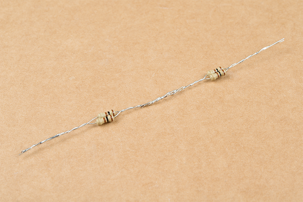
The 50Ω termination will be plugged into the Clock One Output and GND as shown below.

Next, the SparkFun Clock Generator is plugged into the RedBoard Qwiic via the Qwiic cable.
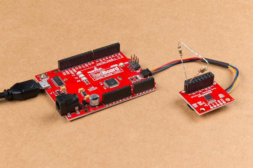
Now the oscilloscope is attached to the terminations as shown below.
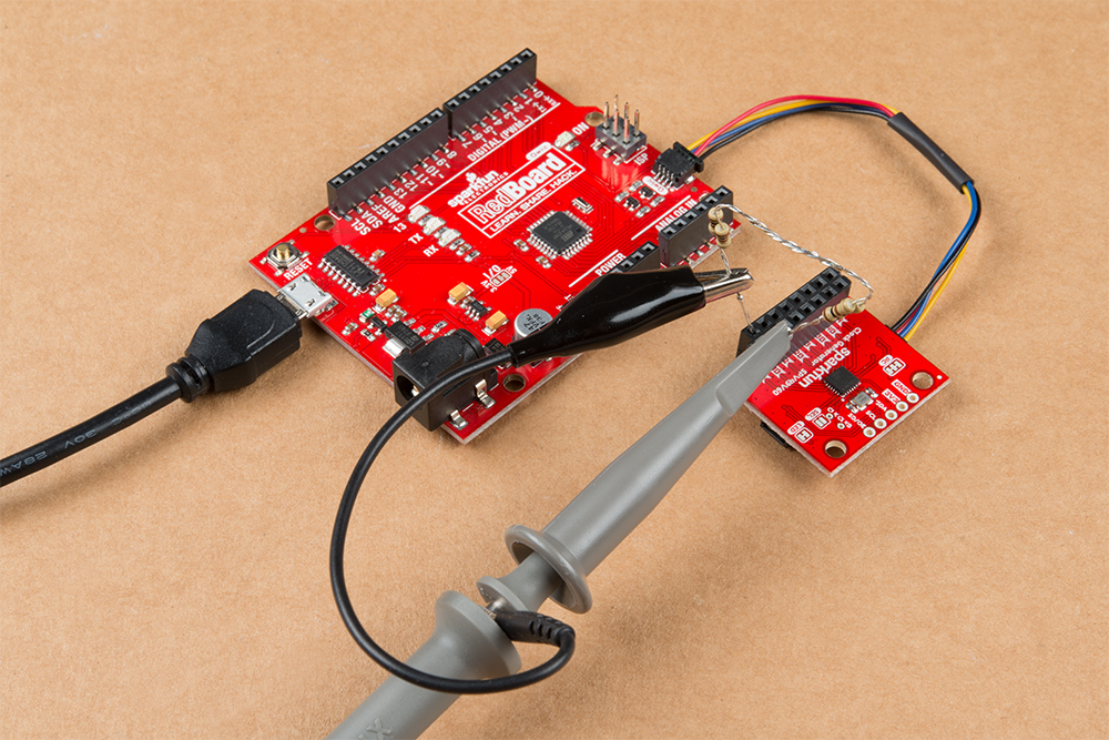
Now if you load up Example 1: Generate a Clock Signal you'll see 16MHz output on the oscilloscope's screen.
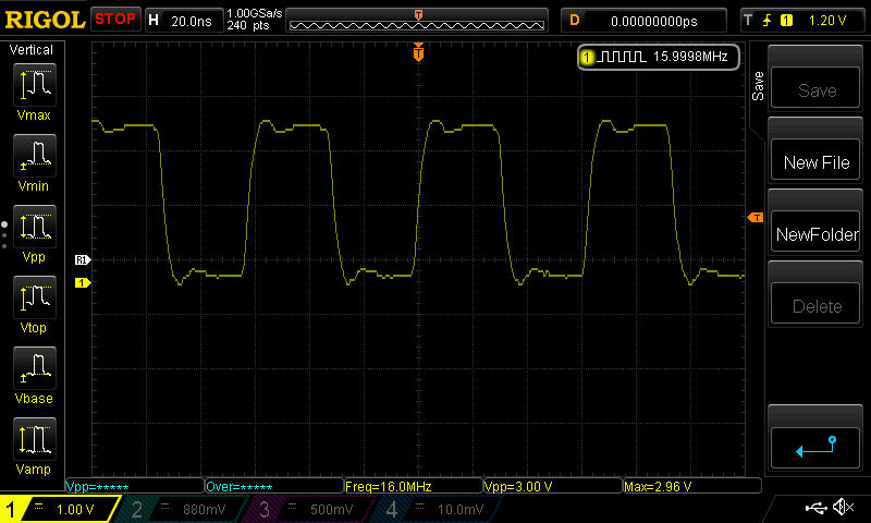
You may notice a bit of over shooting in the picture above and a bit of ringing in the signal. There are a number of reasons why this is happening. I'm terminating my signal on a 1MΩ oscilloscope probe, when I should be using a 50Ω instead. I also have an extended ground cable on the probe, which should be shortened for better signal capture. None the less, I hope that this is still demonstrative of the SparkFun Clock Generator capabilities.
SparkFun Clock Generator 5P49V60 Arduino Library
If you're using the RedBoard Qwiic and have never connected a CH340 device to your computer before, you may need to install drivers for the USB-to-serial converter. Check out our section on How to Install CH340 Drivers for help with the installation
We've written an Arduino library to make it even easier to get started with the SparkFun Clock Generator 5P49V60. The library will give you its' full functionality and provides example code for 90% of the SparkFun Clock Generator's capabilites. You can obtain the library through the Arduino Library Manager by searching SparkFun Clock Generator or you can download the ZIP file below from its GitHub repository to manually install it.
Example 1: Generate a Clock Signal
The first example demonstrates the very basics of the SparkFun Clock Generator: how to generate a clock signal. With the Arduino library installed, click on File > Examples > SparkFun Clock 5P49V60 Arduino Library > Example1_generate clock to follow along with this example. At the top of the example code, the correct library is imported and the microcontroller connects to the SparkFun Clock Generator over the default I2C address: 0x6A.
language:c
#include <Wire.h>
#include "SparkFun_5P49V60.h"

// Uses default address at 0x6A, alternate available at 0x68
SparkFun_5P49V60 clockGen;

void setup(){

  Wire.begin();
  Serial.begin(115200);

  if (clockGen.begin() == true){
    Serial.println("Clock Generator Ready.");
  }
  else {
    Serial.println("Could not communicate with the SparkFun Clock Generator.");
    while(1);
  }
After connecting to the SparkFun Clock Generator, the internal clock frequency of the voltage controlled oscillator is set to 1600MHz (1.6GHz). This frequency can then be fed to the frequency output dividers of the clock outputs. This is done with clockGen.muxPlltoFodOne() which tells the IC to send the VCO frequency to the frequency output divider of clock one. Next the output mode is set to LVPECL_MODE (low voltage positive emitter coupled logic) with clockGen.clockOneConfigMode(LVPECL_MODE).
language:c
  // Fist, Setting the internal oscillator to a known value.
  Serial.println("Setting Internal Clock Frequency to 1600MHz.");
  clockGen.setVcoFrequency(1600.0); // Give float value in MHz.

  // Clock One -----------------------------------------------------
  // Use internal phase lock loop for clock output calculation.
  clockGen.muxPllToFodOne();
  Serial.println("Setting Output Mode to LVPECL.");
  // There are many OUTPUT modes available for each clock - this example uses
  // LVPECL (Low voltage Positive Emitter Coupled Logic) mode.
  clockGen.clockOneConfigMode(LVPECL_MODE);
Finally, the frequency is set to 16MHz by giving a float value of 16.0 to the clockGen.setClockOneFreq() function.
language:c
  Serial.println("Setting Clock One Frequency to 16MHz.");
  clockGen.setClockOneFreq(16.0); // Give float value in MHz, 16.0 = 16000000Hz or 16MHz
  // --------------------------------------------------------------

}

void loop(){

  delay(1000);

}
If you have not already, make sure to select the board (in this case the Arduino/Genuino Uno) and COM port. Then hit the upload button. Connecting the output to an oscilloscope, you should see a waveform similar to the output below when in LVPECL mode. If you decide to use a different mode, make sure to adjust the parameter in clockGen.clockOneConfigMode() and its hardware termination.
Example 2: Generate Multiple Clocks
This example does exactly what the first example does but demonstrates how to also turn on other clock outputs. Click on File > Examples > SparkFun Clock 5P49V60 Arduino Library > Example2_generate_multiple_clocks. This example reinforces how the voltage controlled oscillator frequency is piped to each of the frequency output dividers of the clocks. This doesn't always have to be the case, you can pipe the output of the frequency output divider of one clock to a different output divider to get lower frequencies! Remember that 1MHz is the lowest possible output (clock output frequencies) of any of the frequency output dividers, unless you use this method. Check out example 6 below for more information!
language:c
#include <Wire.h>
#include "SparkFun_5P49V60.h"

// Uses default address at 0x6A, alternate available at 0x68
SparkFun_5P49V60 clockGen;

void setup(){

  Wire.begin();
  Serial.begin(115200);

  if (clockGen.begin() == true){
    Serial.println("Clock Generator Ready.");
  }
  else {
    Serial.println("Could not communicate with the SparkFun Clock Generator.");
    while(1);
  }

  // Fist, Setting the internal oscillator to a known value.
  Serial.println("Setting Internal Clock Frequency to 1600MHz.");
  clockGen.setVcoFrequency(1600.0); // Give float value in MHz
After connecting to the SparkFun Clock Generator, the internal clock frequency of the voltage controlled oscillator is set to 1600MHz (1.6GHz). This frequency can then be fed to the frequency output dividers of the clock outputs. This is done with clockGen.muxPlltoFodOne() and clockGen.muxPlltoFodTwo() which tells the IC to send the VCO frequency to the frequency output divider of clock one and two respectively. Next the output mode is set to LVPECL_MODE (low voltage positive emitter coupled logic) with clockGen.clockOneConfigMode(LVPECL_MODE) and clockGen.clockTwoConfigMode(LVPECL_MODE).
language:c
  // Clock One----------------------------------------------------
  // Use internal phase lock loop for clock output calculation.
  clockGen.muxPllToFodOne();
  Serial.println("Setting Output Mode for Clock One to LVPECL.");
  // There are many OUTPUT modes available for each clock - this example uses
  // LVPECL (Low voltage Positive Emitter Coupled Logic) mode.
  clockGen.clockOneConfigMode(LVPECL_MODE);
  Serial.println("Setting Clock One Frequency to 8MHz.");
  clockGen.setClockOneFreq(8.0); // Give float value in MHz, 8.0 = 8000000Hz or 8MHz
  // --------------------------------------------------------------

  // Clock Two--------------------------------------------------
  // Use internal phase lock loop for clock output calculation.
  clockGen.muxPllToFodOne();
  Serial.println("Setting Output Mode for Clock Two to LVPECL.");
  clockGen.clockTwoConfigMode(LVPECL_MODE);
  Serial.println("Setting Clock Two Frequency to 16MHz.");
  clockGen.setClockOneFreq(16.0); // Give float value in MHz, 16.0 = 16000000Hz or 16MHz
  // -----------------------------------------------------------

}

void loop(){
  delay(1000);
}
Finally, clock one has its frequency set to 8MHz and clock two to 16MHz.
Example 3: Integer and Fractional Divider Calculation
In this example, the division of the reference clock and the division for the frequency output dividers of each clock are set manually. Click on File > Examples > SparkFun Clock 5P49V60 Arduino Library > Example3_int_and_frac_divider_calc to open the example. It's especially beneficial to do this manually when applying fractional values to the frequency dividers. These values often have remainders that must be rounded and thus become the round-off error of your clock output in parts per million (ppm). Knowing this error value could be important to your application. To determine the division values requires some simple math. First, as in the previous two examples the correct libraries are imported and the microcontroller connects to the SparkFun Clock Generator using its' default address: 0x6A.
language:c
void setup(){

  Wire.begin();
  Serial.begin(115200);

  if (clockGen.begin() == true){
    Serial.println("Clock Generator Ready.");
  }
  else {
    Serial.println("Could not communicate with the SparkFun Clock Generator.");
    while(1);
  }
As in the previous sections the voltage controlled oscillator is set to to 1600MHz (1.6GHz). However, the register value must be calculated with some simple math. Our desired input (1600MHz) divided by the frequency of the reference clock (16MHz) equals the divider value 100. Easy Peezy Lemon Squeezy...
language:c
1600/16 = 100
Now we set the register values in code.
language:c
  // Fist, Setting the internal oscillator to a known value that makes for easy
  // division: 1600MHz. 1600MHz/16MHz = 100
  Serial.println("Setting Integer Divider.");
  clockGen.setPllFeedbackIntDiv(100);
  Serial.print("Integer Divider set to: ");
  uint16_t fbVal = clockGen.readPllFeedBackIntDiv();
  Serial.println(fbVal);
The formula for this calculation is in the example sketch's comments. Next the divider values for a frequency of 22MHz is calculated with a similar equation. Divide the voltage controlled oscillator's frequency from above (1600MHz) by two, then divide that value by the desired clock output (22MHz) to get the the clock's frequency output divider's value.
language:c
(1600/2)/22 = 36.3636
This divider value has a decimal and consequently will have two separate values to write to the SparkFun Clock Generator's registers. The first value is the integer portion (36) and the second value is the fractional portion (.36). The integer value can be set as is, but the fractional value first needs additional calculations to translate it into a value the SparkFun Clock Generator expects. To do that we multiply the fractional value by 224 and round that value to the closest integer. The decimal value is the clock output's rounding error in parts per million.
language:c
2^24 * .36 = 6039796.76
.76 = rounding error
76/ppm
Now we write these two values to their registers.
language:c
  // Clock One -----------------------------------------------------
  // To get 16MHz Output = (1600MHz/2)/22MHz = 36.3636
  // Integer portion = 36
  // Fractional portion = .36 -> Need to convert to a HEX value
  // 2^24 * .36 = 6039796.76
  // Round the value to closest integer = 6039797
  clockGen.setIntDivOutOne(36);
  clockGen.setFractDivFodOne(6039797);
  Serial.print("FOD One Integer Divider: ");
  Serial.println(clockGen.readIntDivOutOne());
  Serial.print("FOD One Fractional Divider: ");
  Serial.println(clockGen.readFractDivFodOne());
  clockGen.muxPllToFodOne();
  // There are many OUTPUT modes available for each clock - this example uses
  // LVPECL (Low voltage Positive Emitter Coupled Logic) mode and terminates
  // the clock with a 100Ohm resistance to GND.
  clockGen.clockOneConfigMode(LVPECL_MODE);
  clockGen.clockOneControl(ENABLE);
  // --------------------------------------------------------------

}

void loop(){
  delay(1000);
}
The integer portion is set with clockGen.setIntiDivOutOne(36) and the fractional portion is set with clockGen.setFractDivOut(6039796). These two values are then read back with their respective "read" functions: clockGen.readIntDivOutOne() and clockGen.readFractDivFodOne(). Next we pipe (multiplex) the VCO frequency to the frequency output divider we just set, set the signal type, and enable the clock. In the previous examples, all of the math was done behind the scenes but here doing the math may prove beneficial when needing to know the rounding error.
Example 4 and 5: Change Slew and Skew Clock Signals
The next two examples deal with manipulating the frequencies of the clock outputs. Click on File > Examples > SparkFun Clock 5P49V60 Arduino Library > Example4_change_skew and ... > Example5_change_slew_rate to open the examples. The body of the examples have been reduced to the relevant code blocks in this hookup guide, because the first three examples establish the steps to setup the basics of your SparkFun Clock Generator.
First, the slew rate is modified below by setting it to FAST with the function clockGen.clockOneSlew(FAST). This is one of four settings: SLOWEST, SLOW, FAST, and FASTEST that range from 2.2-2.7 V/ns; see the table above in the Hardware Overview under Clock Output Frequency, for possible settings. After setting the slew rate, the SparkFun Clock Generator is reset with clockGen.globalReset() because changing a clock output's slew rate results in a desychronization of the clock outputs. Global reset is a handy function to keep in your back pocket in case of undesired results.
language:c
// Slew rate for clock one.
Serial.println("Setting Slew Rate.");
clockGen.clockOneSlew(FAST);
Serial.print("Slew rate set, resetting clock signals.");
clockGen.globalReset();
Secondly, the skew rate is set in the following code block. Each clock output is synchronized with each other to maintain a minimal skew rate between them by default. This however, is changed for clock one by calling clockGen.skewClockOne(). In the following code block, clock one is skewed by 10 nano-seconds relative to clock two.
language:c
// Clock One Skew------------------------------------------------
// Clocks are syncronized on every pulse - this skew will ofset clock one by
// 10ns relative to clock two.
clockGen.skewClockOne(10); // Give values in nano seconds.
//---------------------------------------------------------------
Example 6: Multiplex Clock Output
Finally in this last example, the many ways that a clock frequency can be multiplexed through software is demonstrated. Click on File > Examples > SparkFun Clock 5P49V60 Arduino Library > Example6_mux_clock_output to open the example. If, for example, you wanted a lower frequency than the lowest possible frequency output of the frequency output dividers (1MHz), then you can pipe an already low frequency to another divider to get even lower frequencies. Or, if you've set one divider and want that frequency piped out of each output rather than setting each divider, this can also be done. Let's look at the code below.
This example has been reduced to the relevant code block. The first two examples have already demonstrated how to import the correct libraries and connect to the microcontroller to the SparkFun Clock Generator over its default address 0x6A. After setting the internal VCO to 1600MHz, its frequency is piped to the output divider of clock one with clockGen.muxPllToFodOne(). What's important to note is that these values are set manually as in Example 3 because using the more abstract function of clockGen.setClockOne() assumes your piping the VCO frequency to a frequency output divider and NOT, as in this example, piping the output to another frequency output divider.
language:c
  clockGen.setVcoFrequency(1600.0); // Give float value in MHz.
  language:c
  // Clock One -----------------------------------------------------
  // To get 16MHz Output = (1600MHz/2)/16MHz = 50
  clockGen.setIntDivOutOne(50);
  Serial.print("FOD One Integer Divider: ");
  Serial.println(clockGen.readIntDivOutOne());
  clockGen.muxPllToFodOne();
  // There are many OUTPUT modes available for each clock - this example uses
  // LVPECL (Low voltage Positive Emitter Coupled Logic) mode and terminates
  // the clock with a 100Ohm resistance to GND.
  clockGen.clockOneConfigMode(LVPECL_MODE);
  clockGen.clockOneControl(ENABLE);
  // --------------------------------------------------------------
With clock two we see something different. The function clockGen.muxFodOneToFodTwo() takes the output of the frequency output divider for clock one and pipes it to the frequency output divider of clock two. Now this demonstrates its function but doesn't actually divide it a second time.
language:c
  // Clock Two -----------------------------------------------------
  // This function call multiplexes the settings from Clock One's Output
  // Divider to the Output Divider of Clock Two. In this way you can divide a
  // low frequency to get even lower frequencies. The settings for the Clock Two are
  // set to zero so will output a 16MHz frequency.
  clockGen.muxFodOneToFodTwo();
  clockGen.clockTwoConfigMode(LVPECL_MODE);
  clockGen.clockTwoControl(ENABLE);
  // --------------------------------------------------------------
Finally, with clock three the output of clock two is piped to clock three's output, resulting in a round about way of getting three clock outputs to 16MHz. It would have been easier to use the relevant functions to pipe the first output to the next three outputs.
language:c
  // Clock Three -----------------------------------------------------
  // This function call multiplexes the output from clock two to the output of
  // clock three. If you want to duplicate a signal this may be the best
  // option. Notice that you don't need to enable clock three to see an output
  // on this line.
  clockGen.muxOutTwoToOutThree();
  clockGen.clockThrConfigMode(LVPECL_MODE);
  // --------------------------------------------------------------

}

void loop(){
  delay(1000);
}
To summarize there are three avenues that you can multiplex frequencies with the SparkFun Clock Generator. The first is to take the VCO frequency and pipe that to the any of the frequency output dividers. Secondly, you can take the output of the frequency output dividers and pipe them to a the next sequential frequency output divider: FOD1 -> FOD2 -> FOD3 -> FOD4. Finally you can pipe the output of a frequency output divider to any of the next sequential clock outputs: Clock 1 -> Clock 2 -> Clock 3 -> Clock 4.
Resources and Going Further
That SparkFun Clock Generator 5P49V60 is a wildly versatile breakout board. There are still functions of the clock generator for the small sliver of advanced users that were not demonstrated in this hookup guide. Specifically spread spectrum manipulation and one time programming were not explicitly covered but for more information on these topics, check out the resources below:
- Schematic (PDF)
- Eagle Files (ZIP)
- Board Dimensions
- Datasheet (PDF)
- Programming Guide (PDF)
- Arduino Library
- GitHub Repo
- SFE Product Showcase
Need some inspiration for your next project? Check out some of this related tutorial: