Transistors
 jimblom
Applications I: Switches
One of the most fundamental applications of a transistor is using it to control the flow of power to another part of the circuit -- using it as an electric switch. Driving it in either cutoff or saturation mode, the transistor can create the binary on/off effect of a switch.
Transistor switches are critical circuit-building blocks; they're used to make logic gates, which go on to create microcontrollers, microprocessors, and other integrated circuits. Below are a few example circuits.
Transistor Switch
Let's look at the most fundamental transistor-switch circuit: an NPN switch. Here we use an NPN to control a high-power LED:
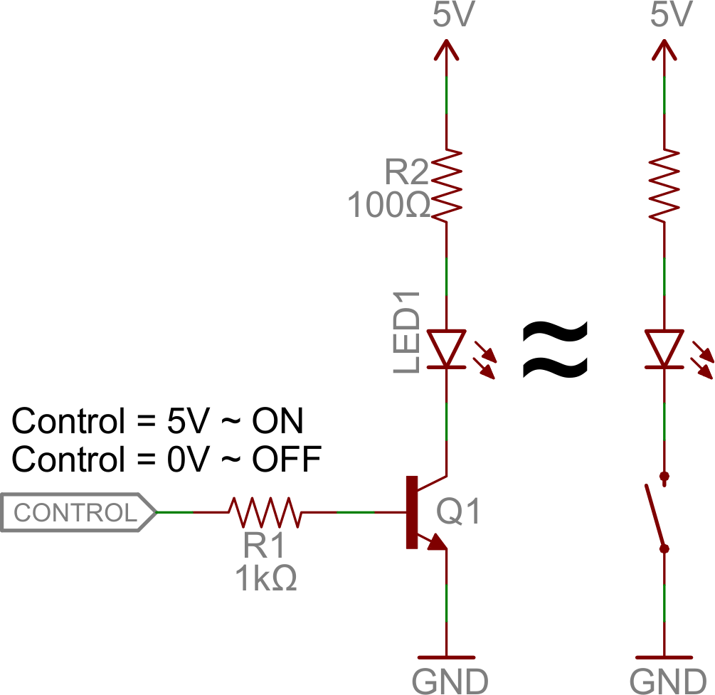
Our control input flows into the base, the output is tied to the collector, and the emitter is kept at a fixed voltage.
While a normal switch would require an actuator to be physically flipped, this switch is controlled by the voltage at the base pin. A microcontroller I/O pin, like those on an Arduino, can be programmed to go high or low to turn the LED on or off.
When the voltage at the base is greater than 0.6V (or whatever your transistor's Vth might be), the transistor starts saturating and looks like a short circuit between collector and emitter. When the voltage at the base is less than 0.6V the transistor is in cutoff mode -- no current flows because it looks like an open circuit between C and E.
The circuit above is called a low-side switch, because the switch -- our transistor -- is on the low (ground) side of the circuit. Alternatively, we can use a PNP transistor to create a high-side switch:
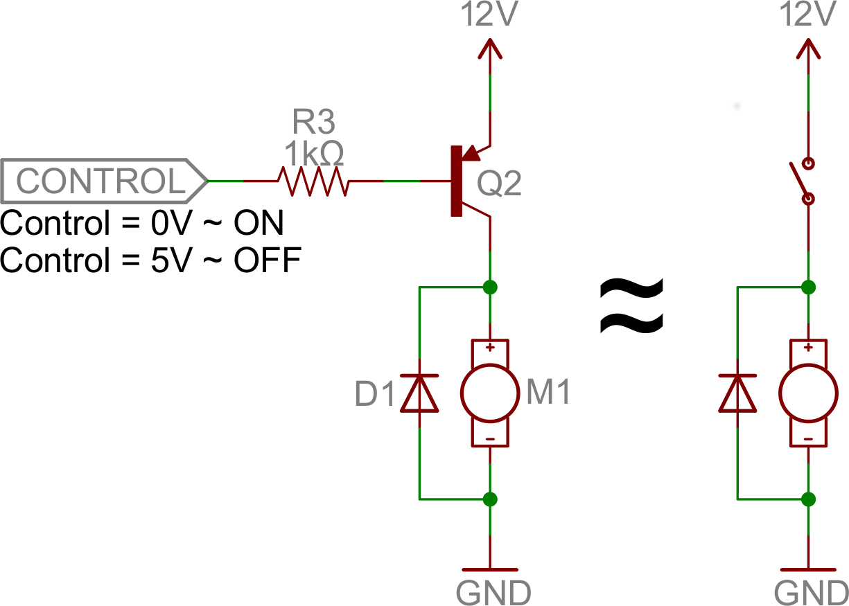
Similar to the NPN circuit, the base is our input, and the emitter is tied to a constant voltage. This time however, the emitter is tied high, and the load is connected to the transistor on the ground side.
This circuit works just as well as the NPN-based switch, but there's one huge difference: to turn the load "on", the base must be low. This can cause complications, especially if the load's high voltage (VCC being 12V connecting to the emitter VE in this picture) is higher than our control input's high voltage. For example, this circuit wouldn't work if you were trying to use a 5V-operating Arduino to switch off a 12V motor. In that case, it'd be impossible to turn the switch off because VB (connecting to the control pin) would always be less than VE .
Base Resistors!
You'll notice that each of those circuits uses a series resistor between the control input and the base of the transistor. Don't forget to add this resistor! A transistor without a resistor on the base is like an LED with no current-limiting resistor.
Recall that, in a way, a transistor is just a pair of interconnected diodes. We're forward-biasing the base-emitter diode to turn the load on. The diode only needs 0.6V to turn on, more voltage than that means more current. Some transistors may only be rated for a maximum of 10-100mA of current to flow through them. If you supply a current over the maximum rating, the transistor might blow up.
The series resistor between our control source and the base limits current into the base. The base-emitter node can get its happy voltage drop of 0.6V, and the resistor can drop the remaining voltage. The value of the resistor, and voltage across it, will set the current.
The resistor needs to be large enough to effectively limit the current, but small enough to feed the base enough current. 1mA to 10mA will usually be enough, but check your transistor's datasheet to make sure.
Digital Logic
Transistors can be combined to create all our fundamental logic gates: AND, OR, and NOT.
(Note: These days MOSFETS are more likely to be used to create logic gates than BJTs. MOSFETs are more power-efficient, which makes them the better choice.)
Inverter
Here's a transistor circuit that implements an inverter, or NOT gate:
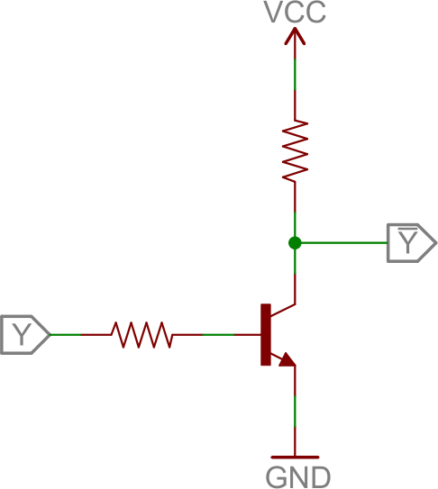
Here a high voltage into the base will turn the transistor on, which will effectively connect the collector to the emitter. Since the emitter is connected directly to ground, the collector will be as well (though it will be slightly higher, somewhere around VCE(sat) ~ 0.05-0.2V). If the input is low, on the other hand, the transistor looks like an open circuit, and the output is pulled up to VCC
(This is actually a fundamental transistor configuration called common emitter. More on that later.)
AND Gate
Here are a pair of transistors used to create a 2-input AND gate:
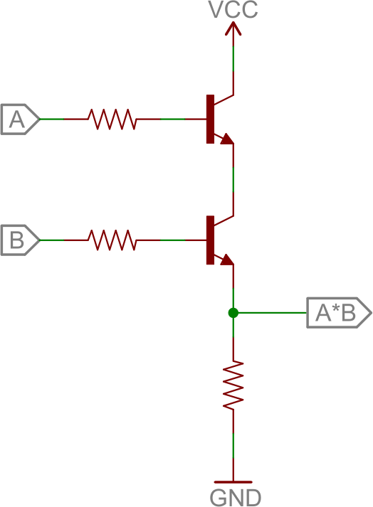
If either transistor is turned off, then the output at the second transistor's collector will be pulled low. If both transistors are "on" (bases both high), then the output of the circuit is also high.
OR Gate
And, finally, here's a 2-input OR gate:
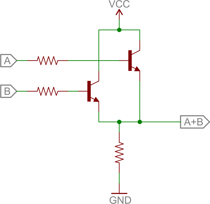
In this circuit, if either (or both) A or B are high, that respective transistor will turn on, and pull the output high. If both transistors are off, then the output is pulled low through the resistor.
H-Bridge
An H-bridge is a transistor-based circuit capable of driving motors both clockwise and counter-clockwise. It's an incredibly popular circuit -- the driving force behind countless robots that must be able to move both forward and backward.
Fundamentally, an H-bridge is a combination of four transistors with two inputs lines and two outputs:
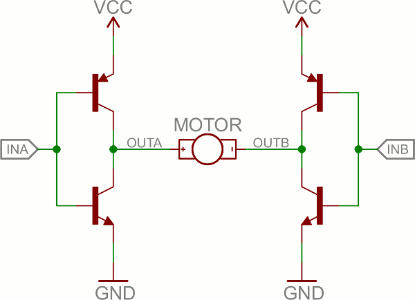
(Note: there's usually quite a bit more to a well-designed H-bridge including flyback diodes, base resistors and Schmidt triggers.)
If both inputs are the same voltage, the outputs to the motor will be the same voltage, and the motor won't be able to spin. But if the two inputs are opposite, the motor will spin in one direction or the other.
The H-bridge has a truth table that looks a little like this:
| Input A | Input B | Output A | Output B | Motor Direction |
|---|---|---|---|---|
| 0 | 0 | 1 | 1 | Stopped (braking) |
| 0 | 1 | 1 | 0 | Clockwise |
| 1 | 0 | 0 | 1 | Counter-clockwise |
| 1 | 1 | 0 | 0 | Stopped (braking) |
Oscillators
An oscillator is a circuit that produces a periodic signal that swings between a high and low voltage. Oscillators are used in all sorts of circuits: from simply blinking an LED to the producing a clock signal to drive a microcontroller. There are lots of ways to create an oscillator circuit including quartz crystals, op amps, and, of course, transistors.
Here's an example oscillating circuit, which we call an astable multivibrator. By using feedback we can use a pair of transistors to create two complementing, oscillating signals.
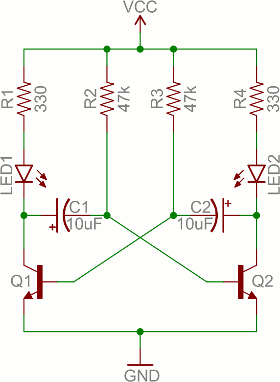
Aside from the two transistors, the capacitors are the real key to this circuit. The caps alternatively charge and discharge, which causes the two transistors to alternatively turn on and off.
Analyzing this circuit's operation is an excellent study in the operation of both caps and transistors. To begin, assume C1 is fully charged (storing a voltage of about VCC), C2 is discharged, Q1 is on, and Q2 is off. Here's what happens after that:
- If Q1 is on, then C1's left plate (on the schematic) is connected to about 0V. This will allow C1 to discharge through Q1's collector.
- While C1 is discharging, C2 quickly charges through the lower value resistor -- R4.
- Once C1 fully discharges, its right plate will be pulled up to about 0.6V, which will turn on Q2.
- At this point we've swapped states: C1 is discharged, C2 is charged, Q1 is off, and Q2 is on. Now we do the same dance the other way.
- Q2 being on allows C2 to discharge through Q2's collector.
- While Q1 is off, C1 can charge, relatively quickly through R1.
- Once C2 fully discharges, Q1 will be turn back on and we're back in the state we started in.
It can be hard to wrap your head around. You can find another excellent demo of this circuit here.
By picking specific values for C1, C2, R2, and R3 (and keeping R1 and R4 relatively low), we can set the speed of our multivibrator circuit:
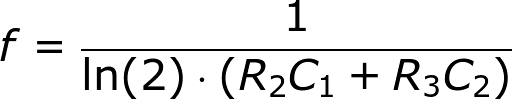
So, with the values for caps and resistors set to 10µF and 47kΩ respectively, our oscillator frequency is about 1.5 Hz. That means each LED will blink about 1.5 times per second.
As you can probably already see, there are tons of circuits out there that make use of transistors. But we've barely scratched the surface. These examples mostly show how the transistor can be used in saturation and cut-off modes as a switch, but what about amplification? Time for more examples!