Transistors
 jimblom
Applications II: Amplifiers
Some of the most powerful transistor applications involve amplification: turning a low power signal into one of higher power. Amplifiers can increase the voltage of a signal, taking something from the µV range and converting it to a more useful mV or V level. Or they can amplify current, useful for turning the µA of current produced by a photodiode into a current of much higher magnitude. There are even amplifiers that take a current in, and produce a higher voltage, or vice-versa (called transresistance and transconductance respectively).
Transistors are a key component to many amplifying circuits. There are a seemingly infinite variety of transistor amplifiers out there, but fortunately a lot of them are based on some of these more primitive circuits. Remember these circuits, and, hopefully, with a bit of pattern-matching, you can make sense of more complex amplifiers.
Common Configurations
Three of the most fundamental transistor amplifiers are: common emitter, common collector and common base. In each of the three configurations one of the three nodes is permanently tied to a common voltage (usually ground), and the other two nodes are either an input or output of the amplifier.
Common Emitter
Common emitter is one of the more popular transistor arrangements. In this circuit the emitter is tied to a voltage common to both the base and collector (usually ground). The base becomes the signal input, and the collector becomes the output.
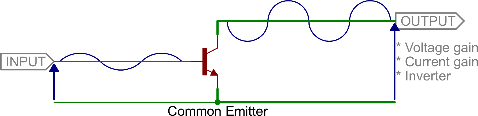
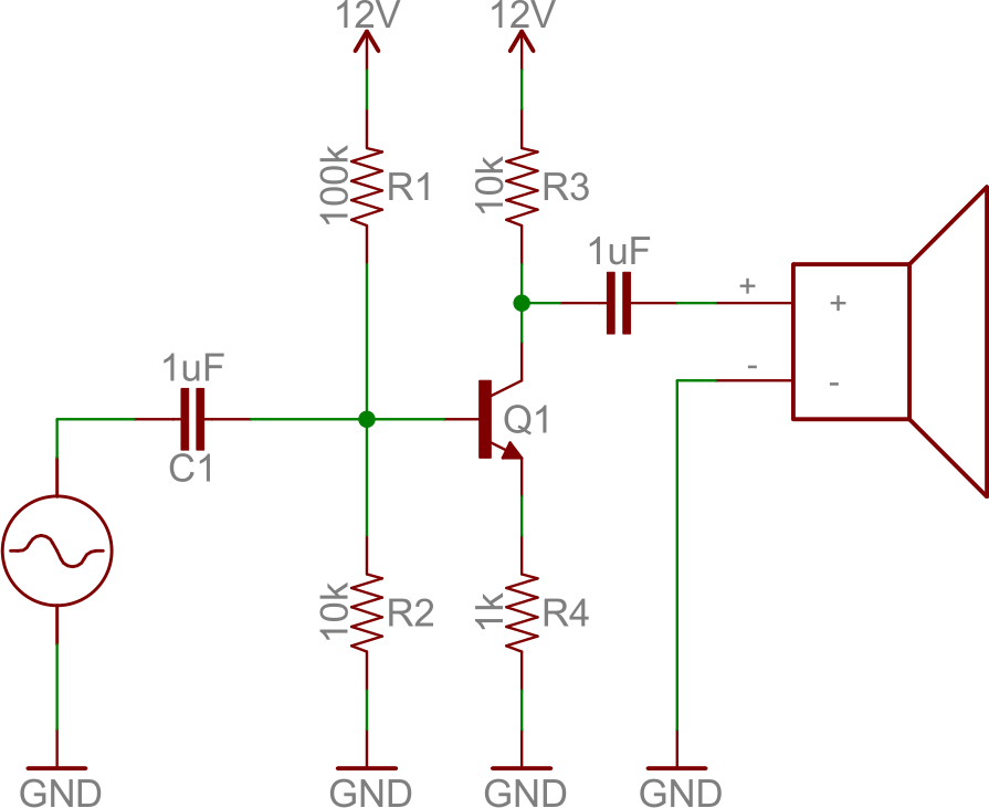
The common emitter circuit is popular because it's well-suited for voltage amplification, especially at low frequencies. They're great for amplifying audio signals, for example. If you have a small 1.5V peak-to-peak input signal, you could amplify that to a much higher voltage using a slightly more complicated circuit, like:
One quirk of the common emitter, though, is that it inverts the input signal (compare it to the inverter from the last page!).
Common Collector (Emitter Follower)
If we tie the collector pin to a common voltage, use the base as an input, and the emitter as an output, we have a common collector. This configuration is also known as an emitter follower.

The common collector doesn't do any voltage amplification (in fact, the voltage out will be 0.6V lower than the voltage in). For that reason, this circuit is sometimes called a voltage follower.
This circuit does have great potential as a current amplifier. In addition to that, the high current gain combined with near unity voltage gain makes this circuit a great voltage buffer. A voltage buffer prevents a load circuit from undesirably interfering with the circuit driving it.
For example, if you wanted to deliver 1V to a load, you could go the easy way and use a voltage divider, or you could use an emitter follower.
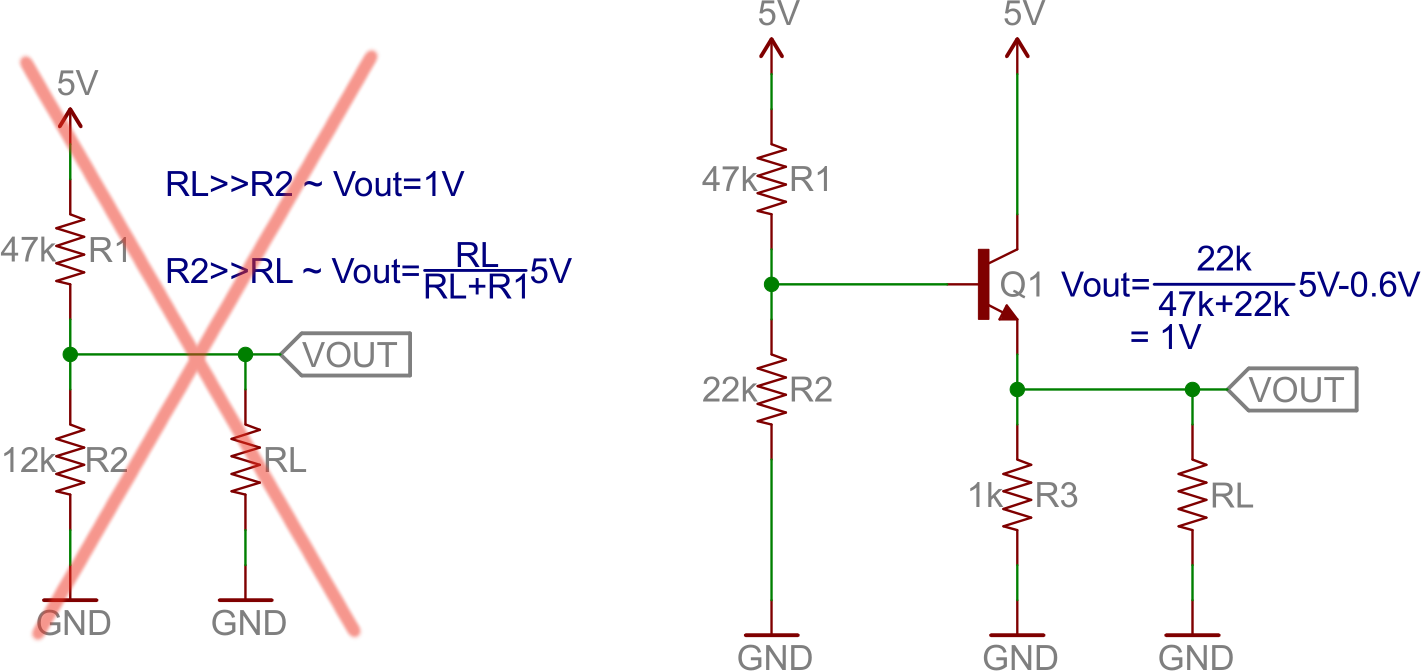
As the load gets larger (which, conversely, means the resistance is lower) the output of the voltage divider circuit drops. But the voltage output of the emitter follower remains steady, regardless of what the load is. Bigger loads can't "load down" an emitter follower, like they can circuits with larger output impedances.
Common Base
We'll talk about common base to provide some closure to this section, but this is the least popular of the three fundamental configurations. In a common base amplifier, the emitter is an input and the collector an output. The base is common to both.
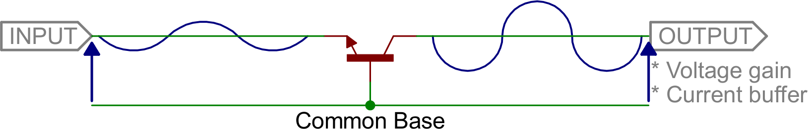
Common base is like the anti-emitter-follower. It's a decent voltage amplifier, and current in is about equal to current out (actually current in is slightly greater than current out).
The common base circuit works best as a current buffer. It can take an input current at a low input impedance, and deliver nearly that same current to a higher impedance output.
In Summary
These three amplifier configurations are at the heart of many more complicated transistor amplifiers. They each have applications where they shine, whether they're amplifying current, voltage, or buffering.
| Common Emitter | Common Collector | Common Base | |
|---|---|---|---|
| Voltage Gain | Medium | Low | High |
| Current Gain | Medium | High | Low |
| Input Impedance | Medium | High | Low |
| Output Impedance | Medium | Low | High |
Multistage Amplifiers
We could go on and on about the great variety of transistor amplifiers out there. Here are a few quick examples to show off what happens when you combine the single-stage amplifiers above:
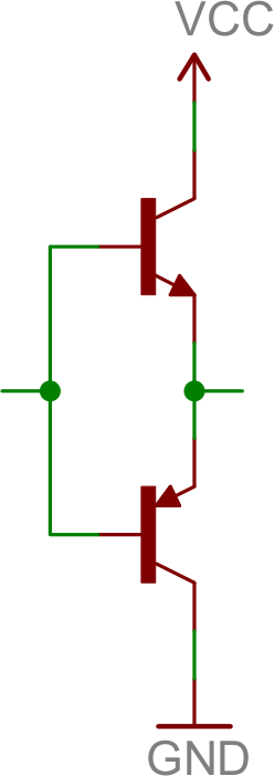
Darlington
The Darlington amplifier runs one common collector into another to create a high current gain amplifier.
Voltage out is about the same as voltage in (minus about 1.2V-1.4V), but the current gain is the product of two transistor gains. That's β2 -- upwards of 10,000!
The Darlington pair is a great tool if you need to drive a large load with a very small input current.
Differential Amplifier
A differential amplifier subtracts two input signals and amplifies that difference. It's a critical part of feedback circuits, where the input is compared against the output, to produce a future output.
Here's the foundation of the differential amp:
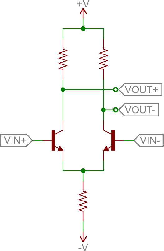
This circuit is also called a long tailed pair. It's a pair of common-emitter circuits that are compared against each other to produce a differential output. Two inputs are applied to the bases of the transistors; the output is a differential voltage across the two collectors.
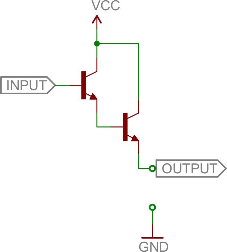
Push-Pull Amplifier
A push-pull amplifier is a useful "final stage" in many multi-stage amplifiers. It's an energy efficient power amplifier, often used to drive loudspeakers.
The fundamental push-pull amp uses an NPN and PNP transistor, both configured as common collectors:
The push-pull amp doesn't really amplify voltage (voltage out will be slightly less than that in), but it does amplify current. It's especially useful in bi-polar circuits (those with positive and negative supplies), because it can both "push" current into the load from the positive supply, and "pull" current out and sink it into the negative supply.
If you have a bi-polar supply (or even if you don't), the push-pull is a great final stage to an amplifier, acting as a buffer for the load.
Putting Them Together (An Operational Amplifier)
Let's look at a classic example of a multi-stage transistor circuit: an Op Amp. Being able to recognize common transistor circuits, and understanding their purpose can get you a long way! Here is the circuit inside an LM3558, a really simple op amp:
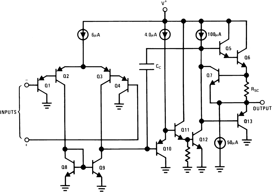
There's certainly more complexity here than you may be prepared to digest, however you might see some familiar topologies:
- Q1, Q2, Q3, and Q4 form the input stage. Looks a lot like an common collector (Q1 and Q4) into a differential amplifier, right? It just looks upside down, because it's using PNP's. These transistors help to form the input differential stage of the amplifier.
- Q11 and Q12 are part of the second stage. Q11 is a common collector and Q12 is a common emitter. This pair of transistors will buffer the signal from Q3's collector, and provide a high gain as the signal goes to the final stage.
- Q6 and Q13 are part of the final stage, and they should look familiar as well (especially if you ignore RSC) -- it's a push-pull! This stage buffers the output, allowing it to drive larger loads.
- There are a variety of other common configurations in there that we haven't talked about. Q8 and Q9 are configured as a current mirror, which simply copies the amount of current through one transistor into the other.
After this crash course in transistors, we wouldn't expect you to understand what's going on in this circuit, but if you can begin to identify common transistor circuits you're on the right track!