In this tutorial, we will utilize MakeCode's radio blocks to have one micro:bit transmit a signal to a receiving micro:bit on the same channel. Eventually, we will control a micro:bot wirelessly using parts from the micro:arcade kit!
To follow along with this tutorial, you will need the following materials at a minimum. You may not need everything though depending on what you have. Add it to your cart, read through the guide, and adjust the cart as necessary.
The following materials are optional to make a battle bot.
If you aren’t familiar with the following concepts, we recommend checking out these tutorials before continuing.
To make the most out of the carrier boards with the least amount of coding, use the Microsoft MakeCode extensions written for the gamer:bit and moto:bit boards. If you have not already, check out the instructions for installing the extensions for both boards as explained in their respective guides whenever you make a new MakeCode project utilizing the boards.
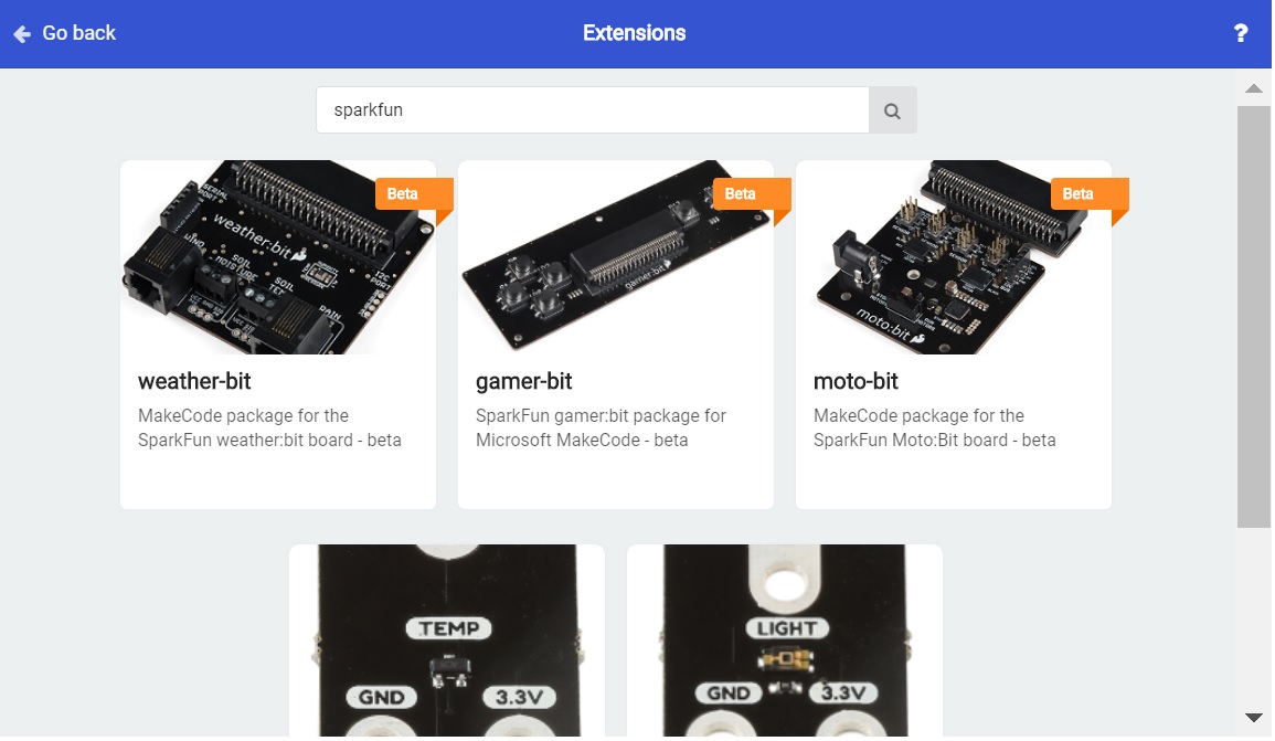
To install the extension for the controller:bit (formerly known as the gamer:bit, head over to our micro:arcade kit experiment guide to follow the instructions.
To install the extension for the moto:bit, head over to our micro:bot kit experiment guide to follow the instructions.
There are a few methods of transmitting data between two or more micro:bits. You can send a number, or a string. For simplicity, we will send one number between two micro:bits.
radio code blocks? Try looking at the MakeCode reference guide!
You will need the following parts:
For a few items listed, you will need more than one unit (i.e. micro:bits, micro-B USB cables, etc.). You may not need everything though depending on what you have. Add it to your cart, read through the guide, and adjust the cart as necessary.
For this part of the experiment, we are going to send a number from one micro:bit to another micro:bit on the same channel.
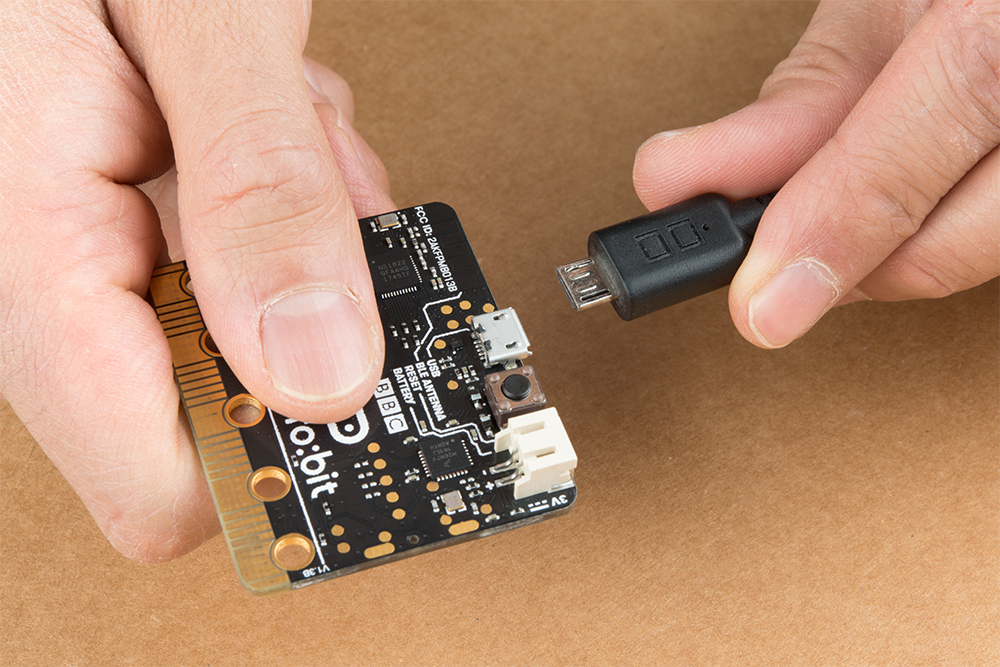
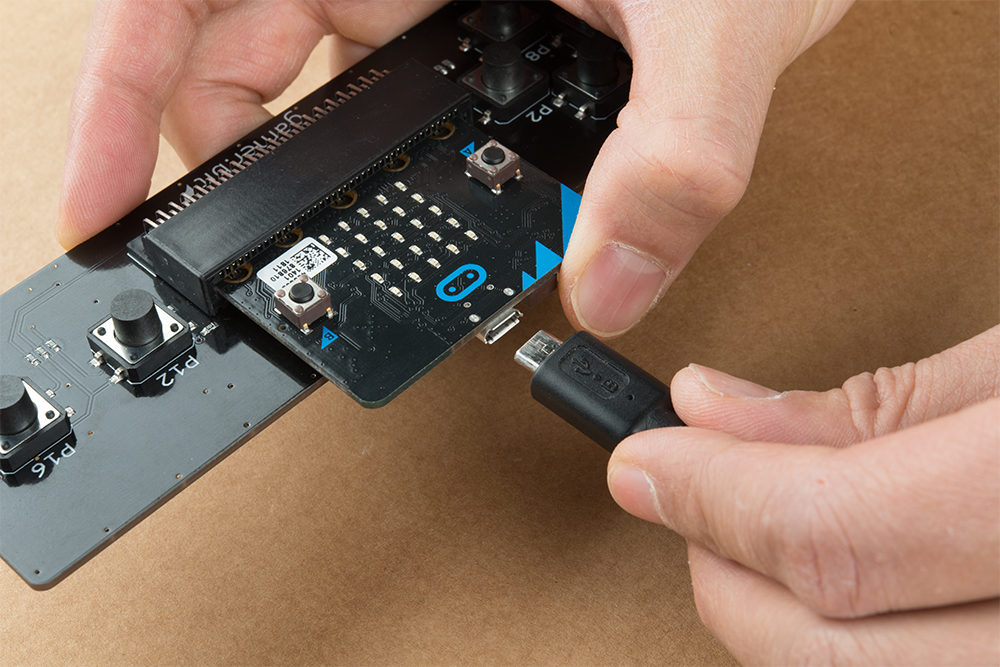
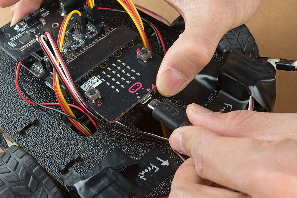
Connect the first micro:bit to your computer via USB cable.
We are going to use Microsoft MakeCode to program the micro:bit. You can download the following example script and move the *.hex file to your micro:bit. Or use it as an example to build it from scratch in MakeCode.
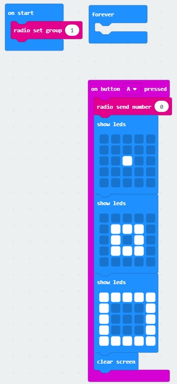
When the micro:bit is powered up, we'll want it set up the radio to a certain channel. In this case, we head to the Radio blocks, grab the radio set group __ block, and set it to 1. We will use the built-in button A on the micro:bit. From the Input blocks, we use the on button A pressed, Once the button is pressed, we will transmit a number 0 wirelessly. For feedback, we will use the Basic blocks to have the LEDs animate with a dot expanding out into a square to represent a signal being sent out. Once the animation is finished, we will clear the screen.
For this part of the experiment, we are going to have a second micro:bit receive a number from the first micro:bit.
To avoid confusion when uploading code, unplug the first micro:bit from your computer. Then connect the second micro:bit to your computer via USB cable.
Download the following example script and move the *.hex file to your micro:bit. Or use it as an example to build it from scratch in MakeCode. You will need to open a new project to receive the data from the first part of this experiment.
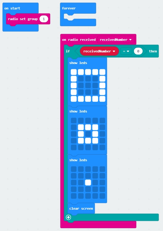
When the second micro:bit is powered up, we'll want to set the radio to the same channel as the first micro:bit. In this case, it will be 1. Using the on radio received __________ block, we will want to check to see what signal was received. In this case, we will want to check for a receivedNumber that is equal to 0 since a number was sent from the first micro:bit. Using the if statement from the Logic blocks, we will want to check if the variable holding the received number matches 0. If it matches, we will want the micro:bit to do something. Visually, using LEDs would be the easiest so an animation of a square shrinking to a dot was chosen to represent the received signal. Once the animation is finished, we will want to clear the screen until we receive another signal.
Pressing on button A with the first micro:bit (our transmitting) will send a number out in channel 1. In this case, the number that is transmitted is 0.
The second micro:bit (our receiving) will take that number that was sent on channel 1 and do something based on the condition statement. In this case, there is an animation using the LED array to indicate when we have received the number.
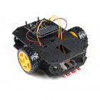
Remember our micro:bot? The micro:bot was running around loose by itself the last time we were working with the robot. Let's give it some commands so that it only moves when you want it to using the controller:bit carrier board!
You will need the following parts:
For a few items listed, you will need more than one unit (i.e. micro:bits, AA batteries, etc.). You may not need everything though depending on what you have. Add it to your cart, read through the guide, and adjust the cart as necessary.
For this part of the experiment, we will use the same method as experiment 1 to transmit a command. As soon as a certain combination of buttons are pressed on the controller:bit, the attached micro:bit will transmit one command to a receiving micro:bit. For debugging purposes, we are going to have a short animation when the buttons are pressed for feedback.
If you have not already, insert one micro:bit into the controller:bit's carrier board. Make sure to insert the micro:bit with the LED array facing up (the same direction as all of the buttons) as explained in the micro:arcade kit experiment guide. We’re continuing on from experiment 3. Make sure to check out the guide before continuing on.
Then connect the micro:bit to your computer via USB cable.
Download the following example script and move the *.hex file to your micro:bit. Or use it as an example to build it from scratch in MakeCode. Remember, if you are building from scratch, you will need to install the appropriate extension when using the controller:bit.
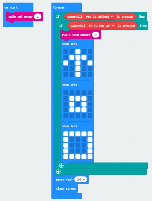
When the micro:bit is powered up, we'll want it set up the radio to a certain channel. In this case, we set the radio block to 1 just like experiment 1. Then we'll want to check if the P16 button is pressed on the controller:bit, just like an accelerate button used in driving games. For simplicity, we will want the robot to move forward when pressing the up (P0) button on the direction pad. We will be using a nested if statement to check on the buttons defined in the gamer:bit extension. A nested if statement is one or more if statements "nested" inside of another if statement. If the parent if statement is true, then the code looks at each of the nested if statements and executes any that are true. If the parent if statement is false, then none of the nested statements will execute. By using the logic statement, we will be using the gamer:bit ____ is pressed block.
Once both buttons are pressed, we will send a command out. In this case, it will be number 0. For feedback, to see if our code works as expected, we will have the LEDs animate with an arrow pointing up and a square growing bigger. We then give the micro:bit a short pause before clearing the screen and looping back to the beginning of the forever loop.
In this part of the experiment, we need to have a receiving micro:bit recognize the command that was sent from the first micro:bit in order to control the micro:bot. For simplicity, we will have the robot drive forward. To debug, the LED array will display an arrow to indicate the direction where the robot should move for feedback.
At this point, you should have your micro:bot kit assembled! We're continuing on from experiment 5. Make sure to check out the guide before continuing on.
To avoid confusion when uploading code, unplug the first micro:bit from your computer. Connect the second micro:bit to your computer via USB cable.
Download the following example script and move the *.hex file to your micro:bit. You can also use it as an example to build it from scratch in MakeCode. Remember, if you are building from scratch, you will need to install the appropriate extension when using the moto:bit.
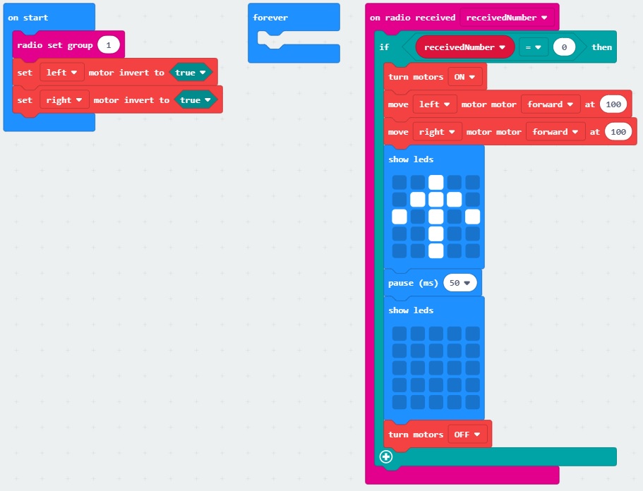
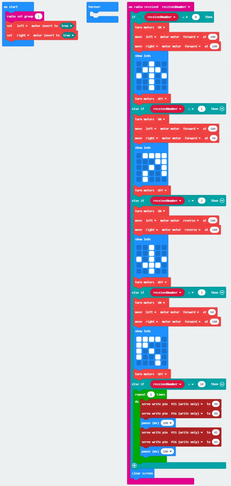
When the second micro:bit is powered up, we'll want to set the radio to the same channel as the first micro:bit; again to 1. As explained in the micro:bot experiment guide, we will want to set the left and right motors' logic based on the way we connected the motors to the motor:bit. For consistency, we will make both true. Using the on radio received __________ block from the moto:bit extension, we will want to check to see what command was received. In this case, it should be a 0 that was sent from the first micro:bit. If the command that was sent matches 0, we will want the moto:bit to drive forward at 100%. For feedback, we will have an arrow point up. After a short pause of about 50ms, we will want to clear the screen and turn the motors off before checking again. If the pause is too long, the micro:bot will continue to drive forward even after you remove your fingers from the controller:bit's buttons.
Now that both micro:bits are programmed, let's the test code out. Disconnect the USB cables from both micro:bits and power each with the respective battery packs.
 |
 |
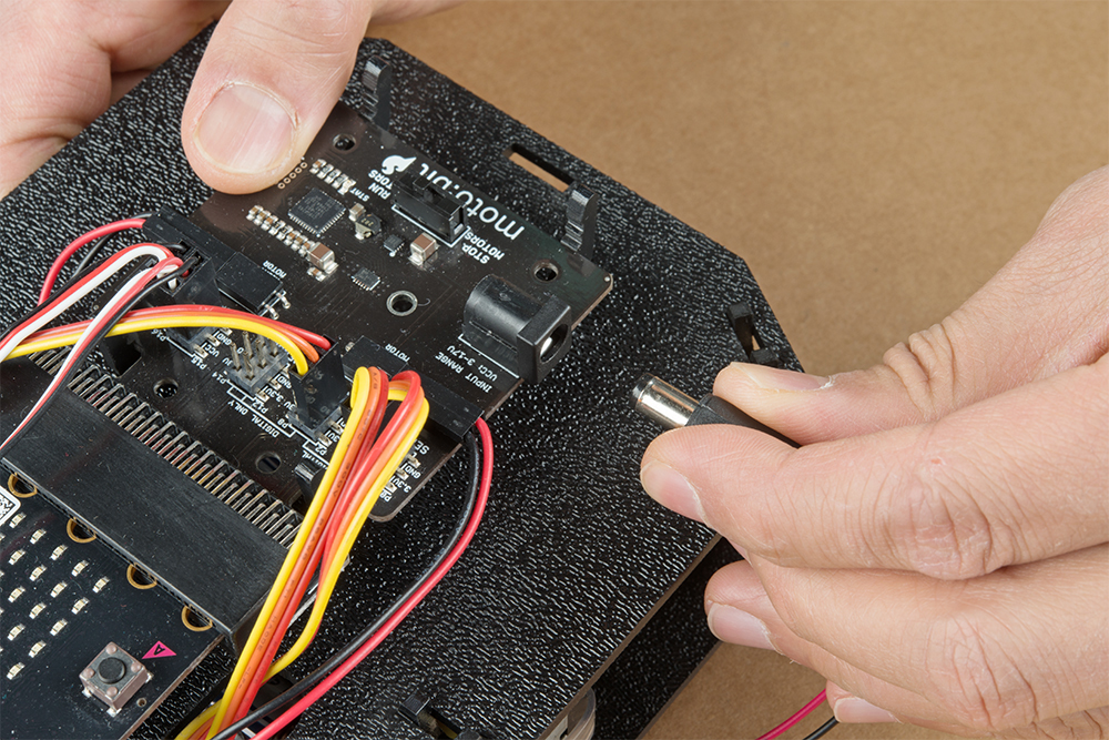
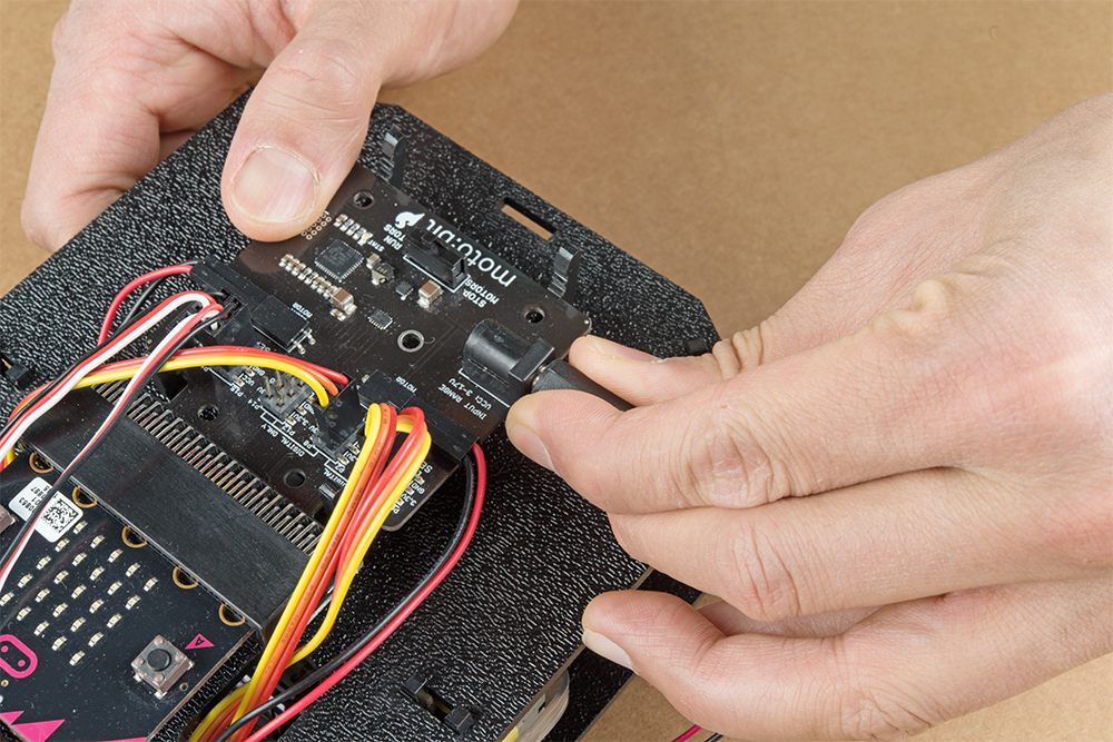
For the micro:bot, insert the 4xAA battery pack into the barrel jack.
 |
 |
Then move the switch labeled as RUN MOTORS to the ON position. Pressing on the drive button (P16) and up button (P0) on the controller:bit will cause the micro:bot to drive forward. You should also see the LED array animate.
Now that we are able to wirelessly move our robot forward, we will want additional commands for turning and driving in reverse. While we are at it, we are going to give a special function to control the servos attached to our battle bot.
You will need the following parts:
For a few items listed, you will need more than one unit (i.e. micro:bits, AA batteries, etc.). You may not need everything though depending on what you have. Add it to your cart, read through the guide, and adjust the cart as necessary.
For this part of the experiment, we will repeat the steps in 2.1 to transmit commands for turning or driving in reverse. The built-in accelerometer will be used to detect a shake. A command to control the servo motors will be sent out as soon as there is a shake detected.
If you have not already, insert one micro:bit into the controller:bit's carrier board. Make sure to insert the micro:bit with the LED array facing up (the same direction as all of the buttons) as explained in the micro:arcade kit experiment guide. We’re continuing on from experiment 3. Make sure to check out the guide before continuing on.
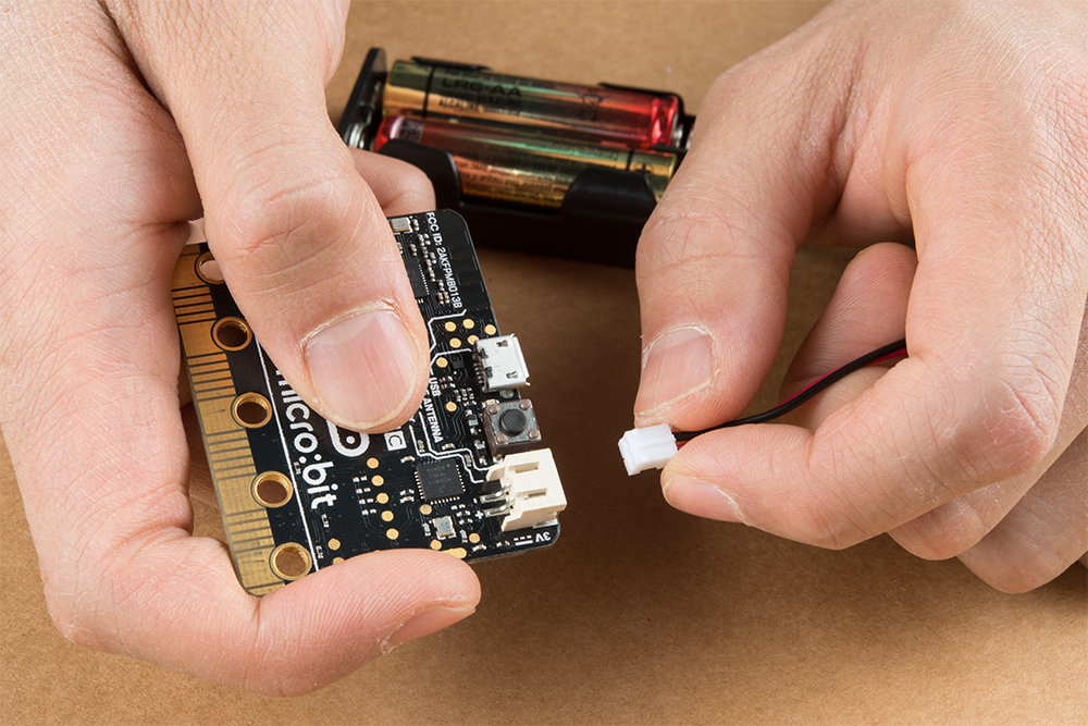
Disconnect the battery pack from micro:bit from the previous experiment. The JST connector is a tight fit in the micro:bit so you will need to carefully remove the connector out by wiggling it side to side using your index finger and thumb. It is easier to remove the micro:bit from the controller:bit carrier board.
Then connect the first micro:bit to your computer via USB cable.
Download the following example script and move the *.hex file to your micro:bit. Or use it as an example to build it from scratch in MakeCode. You will need to open a new project to receive the data from the first part of this experiment. Remember, if you are building from scratch, you will need to install the appropriate extension when using the controller:bit.
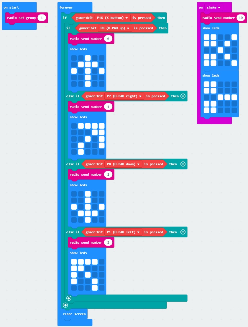
Using the same template for driving forward, we assign a unique number to the right (P2), down (P8), and left (P1) buttons on the direction pad. For simplicity, we will just want the robot to move forward when turning right or left. There is not as much animation with the LED array in this example since it can slow down your micro:bit. Using the Input's on shake block from the Input, a unique number is sent out to control the servos. Again, an arrow will display briefly for feedback in each case.
For this part of the experiment, we will repeat the steps in 2.2 to receive the commands before moving the robot. Instead of just driving forward, the robot can now turn, reverse, and control the servo motors.
We'll be using the same servo connection on the battle bot as explained in experiment 5. Make sure to check out the guide before continuing on.
Remove the battery pack from the moto:bit carrier board from the previous experiment.
To avoid confusion when uploading code, unplug the first micro:bit from your computer. Then connect the second micro:bit to your computer via USB cable.
Download the following example script and move the *.hex file to your micro:bit. Or use it as an example and build it from scratch in MakeCode. You will need to open a new project to receive the data from the first part of this experiment. Remember, if you are building from scratch, you will need to install the appropriate extension when using the moto:bit.
We set up the second micro:bit to use the same channel and motor logic as explained in experiment 2.2. Four more commands were added to the on radio received __________ to turn right, reverse, turn left, and control the servo motors of our battle bot. When turning, the motor closest to the inside of the turn is set to a lower value. That way the robot will continue to drive forward but also move right or left. To reverse, both motors used the reverse option to drive backwards. Finally, if the robot receives a command indicating that there was a shake from the first micro:bit, the servos will move. If you look closely at the receivedNumber, each of the commands match the same number that was transmitted from the first micro:bit.
Now that both micro:bits are programmed with more commands, let's test the code out. Disconnect the USB cable from both micro:bits and power each with the respective battery packs again.
|
|
Pressing the controller:bit's drive button (P16) and any of the buttons located in the direction pad (P0, P2, P8, P1) will cause the robot to move. Shaking the first micro:bit will make the servos on the micro:bot move.
When finished, make sure to power down your controller and micro:bot by disconnecting the JST connector and barrel jack on the battery packs. This will save you some power in the long run for more fun! Again, the JST connector is a tight fit in the micro:bit so you will need to carefully remove the connector out by wiggling it side to side using your index finger and thumb.
|
|
Instead of sending a number, try adjusting the code to transmit a value or string between the two micro:bits.
Try adjusting experiment 1's code to have the second micro:bit send a signal back to the first micro:bit.
Have more than two micro:bits? Try modifying code to broadcast a signal from one micro:bit to several micro:bits by having the receiving micro:bits on the same channel! Or try coding with a friend to make two micro:bits fighting for control of a third micro:bit attached to a micro:bot.
Ok, so experiment 3 did not have "all" the specified movements. We just gave some basic movements so that the micro:bot can move around the floor. Try adjusting the codes to turn when the micro:bot is moving backwards. Can you adjust the code so that the robot can rotate without driving forward or back? Or maybe program the robot to dance when a certain button(s) are pressed.
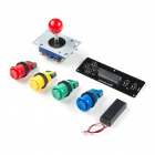
Go retro and wire the gamer:bit with the joystick and buttons for a different style controller. The joystick and buttons are great for more intense gamers.
Try flipping the control of the buttons and sensors. Instead of using the buttons to control the robot's motion, try using the accelerometer or magnetometer. Can you control the motor intensity based on the sensor reading? Then, to control the battle bot's servos, try using the buttons.
Try using parts from the micro:climate kit to relay sensor data and monitor an environment at a distance between two micro:bits.
Not working as expected? Below are a few troubleshooting tips to get your micro:bits working as expected. For your convenience, relevant troubleshooting tips from the micro:arcade and micro:bot experiment guides were included below.
Not Receiving a Signal?
The Second Micro:bit is Reacting Without Sending Data from the First Micro:bit.
Micro:bit is Not Showing Up.
Gamer:bit or Moto:bit Blocks are Not Visible.
Robot Not Driving Straight!
forward or reverse. Robot is Not Moving After Sending a Command from the Gamer:bit.
Moving in Reverse?!
set ____ motor invert to ____ block in your on start block to change what is forward vs. reverse. Servo Moves in the Wrong Direction.
Servo Doesn't Move at All!
Now that you've successfully got your micro:bits communicating, it's time to incorporate it into your own project! Need some inspiration? Check out our other robots found in our robotics section.
Looking for more wireless fun? Check out the following using wireless applications.
Or try checking out these cool robots from AVC.
learn.sparkfun.com | CC BY-SA 3.0 | SparkFun Electronics | Niwot, Colorado